The evolution of Polytetrafluoroethylene (PTFE) – more commonly known as Teflon® – from a niche product used only in high-value applications to a mainstream requirement has been very gradual.
However, over the past two decades PTFE usage seems to have crossed a critical mass, allowing it to become commercially viable in over 200 industrial, consumer and medical applications. And while sheets, rods, coatings and components corner the bulk of the market for PTFE products, PTFE tubing and PTFE hose are now emerging as the key growth area.
PTFE tubing applications
The use of PTFE tube has spread across various applications including automotive, chemical, electrical and medical. Table 1 shows the key properties which outline the versatility of PTFE tubing, while Fig 1 shows its uses in various fields.
- In automotive applications, the ability of PTFE to withstand temperatures in excess of 250oC makes it an ideal candidate for high temperature fluid transfer.
- In medical applications, PTFE tubing is in huge demand due to its lubricity and chemical inertness. Catheters employing PTFE tubing can be inserted into the human body without fear of reaction or abrasion with any body parts.
- In chemical applications – including laboratories – PTFE is an ideal replacement for glass due to its inertness and durability.
- In electrical applications, the excellent dielectric properties of virgin PTFE make it well suited for insulating high voltage cables.
|
Property
|
Comments
|
Applications
|
|
Heat resistance
|
- Working temperature range of -260 to +260oC
- Melting point of 327oC
|
- High temperature fluid transfer
- Insulation of metal parts
|
|
Dielectric strength
|
- Working range of 50-120 Kilo volts per mm
|
- Insulation of electrical cables
|
|
Low friction
|
- Coefficient of friction of 0.1
- Almost identical static and dynamic coefficients
|
|
|
Corrosion resistance
|
- Water absorption at 0%
- Chemically inert - affected only by molten alkali metals, fluorine and chlorine trifluoride at elevated temperatures and pressures
|
- Chemical substances transfer
- Protection of metal parts
|
Table 1: Key properties and applications of PTFE tubing
Types of PTFE tubing
Depending on the application, PTFE tubing is divided into three broad categories – each defined by the tube’s diameter and the wall thickness (see Table 2).
|
|
Diameter (mm)
|
Wall thickness (mm)
|
|
Spaghetti tubing
|
0.2-8
|
0.1-0.5
|
|
Pressure hose
|
6-50
|
1-2
|
|
Pipe Liner
|
12-500
|
2-8
|
Table 2: Categories of PTFE tubing
Even within categories, PTFE tubing lends itself to different variations, each allowing for a different application (see Table 3):
|
Type
|
Description
|
Purpose
|
|
Multi-lumen
|
Single outer tube with multiple inner tubes
|
Each inner tube holds a different fluid/ wire - useful in medical applications
|
|
Split
|
Ridge on tube wall allowing it to be split longitudinally
|
Surgeon can remove a PTFE introducer from a patient while the primary device remains in place
|
|
Corrugated/ convoluted
|
Folds on outer wall
|
Gives higher bend-ability, reducing risk of kinks when tube is passed through tight angles
|
|
Heat shrinkable
|
Thin tubing which shrinks in diameter when hot air is applied to it
|
Used to sheath wires, glass tubes for insulation or protection
|
|
Filled
|
Chemical additive giving radiopaque properties
|
Used in medical inserts - to show up in X-rays
|
Table 3: Variants of PTFE tubing
PTFE tubing in the medical device market
In general, small diameter spaghetti tubing is used in medical applications. The use of PTFE in this area centers on two key properties: lubricity and biocompatibility. Fluoropolymers exhibit very good lubricity compared with other plastics. PTFE is the most lubricious polymer available, with a coefficient of friction of 0.1, followed by fluorinated ethylene propylene (FEP), with 0.2. These two polymers represent the vast majority of all fluoropolymer tubing used in medical devices.
The biocompatibility of any polymer used in a medical device is an obvious concern. PTFE excels in this area and has a long history of in vivo use. Medical-grade fluoropolymers should meet USP Class VI and ISO 10993 testing requirements. Of course, processing cleanliness is also an important factor.
PTFE tubing – processing techniques
The uniqueness of PTFE tubing rests in the complexity of PTFE as a polymer. While most polymers lend themselves easily to injection moulding – allowing them to be made into complex shapes, PTFE due to its high melting point and melt viscosity can only be compression moulded. The high melting point of PTFE also means that extrusion – as conventionally practiced – cannot be applied to it. PTFE paste extrusion has therefore become a process which is increasingly sought after – given the growing demand for PTFE tubing.
Extruded grades of PTFE were first used in the wire and cable industry in the 1950s, where the good dielectric properties of the material proved critical to the developing electronics market. The first tubing was made by extruding PTFE over a wire and then removing it-a labour-intensive process. In the 1960s, technology emerged that could perform the extrusion of PTFE without a wire core. This process enables PTFE tubing to be economically produced in long continuous lengths.
PTFE paste extrusion follows 6 broad steps as illustrated below:
- Mixing: The resin comes in a powder form with an average particle size of about 0.2µm. The powder is waxy and prone to bruising and mechanical shear fibrillation. Hence handling must be careful and done typically at a temperature of around 20°C. While standard compression moulding only requires that the powder be sieved thoroughly and then compressed, in paste extrusion the powder must be first mixed with a hydrocarbon extrusion aid or mineral spirits. The powder-spirit mixture is left in a sealed container before it is used in the next process
- Pre-form: The pre-form is a billet made by compressing the mixture in a hydraulic press. A standard 30Kg billet would take approximately 2 hours to mould, following which a dwell time is necessary to ensure any excess air pockets get released
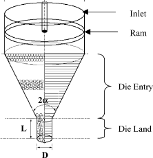
- Extruding: the pre-form is loaded into the extruder – the key equipment in the process – and a die and mandrel are clamped in place above it. The die is a critical tool and its design defines the strength of the tube and its final dimensions. As the extrusion process starts, the extruder presses the pre-form against the die and mandrel, forcing the resin to extrude into the desired shape. The tubing in this stage is referred to as ‘green’ and can be easily crushed.
- Pre-sintering: the green tubing is passed through an oven where it is heated at a very low temperature. The idea here is to evaporate the spirit in the tube and care must be taken so that the flash point of the spirit is not reached, causing it to ignite.
- Sintering: the PTFE tubing is sintered at 350-400°C. The sinter cycle will depend on the thickness of the tubing and can last up to 24 hours for thick walled tubing
- Cleaning and packaging: the tube is first cut into he desired lengths. In the case of medical tubing, the ends of the tube must be plugged as soon as the material comes out of the oven. The plugging ensures that the inside of the tubing – which has seen temperatures well in excess of 300°C – remains clean. For further cleaning an ISO Grade VI clean room is the minimum requirement for PTFE tubing. After the cleaning the tubes are packed in polythene covers for dispatch.
Fig 1: Typical extrusion die
PTFE Tubing and Poly Fluoro Ltd. - FluoroTube™
Poly Fluoro Ltd. was established in 1985 – at a time when India was not yet fully aware of the properties of PTFE material or its usefulness across so many industries.
The company has built its expertise in mainly industrial applications – making machine components, slideway bearing materials (Turcite/Lubring) and PTFE tapes – and become a reputable player in the industry.
More recently, Poly Fluoro Ltd. has embarked on a plan to strengthen its presence in medical applications. With this in mind, the company has invested heavily in developing laboratory wares, PTFE coated guidewires (used extensively in urology) and PTFE tubing.
FluoroTube™ marks the entry of Poly Fluoro Ltd. into the PTFE tubing segment. With this product, Poly Fluoro is looking to build a tubing brand, which assures the client the highest quality of PTFE tubing.
FluoroTube™ will also be the first PTFE tubing manufactured in India – giving the local market
PTFE tubing at a price point that would greatly improve their cost dynamics and allow the full demand for PTFE tubing to be met in India.
The grades and sizes available make FluoroTube™ ideal for applications such as medical, chemical and automotives.
FluoroTube™ comes in sizes ranging from 1mm to 25mm diameters and is unique in many ways when compared to conventional polymer tubing. Table 3 shows the technical properties for FluoroTube™.
In the near future, Poly Fluoro will also be embarking on the manufacture of FEB Tubes and FEP hose. FEP belongs to the same family of PTFE, but being melt processable, the material can be drawn into longer tubes with far thinner wall thicknesses. The entry into FEP will again see Poly Fluoro as pioneers into a new area of fluoroplastics manufacturing.
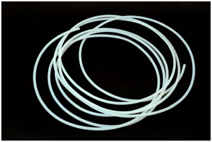
Fig 2: FluoroTube™
Table 3 : Technical specifications of FluoroTube
| Property |
ASTM test |
Value |
|
Physical properties
|
|
|
| Specific gravity |
D792 |
2.15 |
| Water absorption ( % ) |
D570 / 24 hrs 1/3" t |
< 0.00 |
| Mold shrinkage ( cm / cm ) |
|
0.02 – 0.05 |
| Contact angle ( degree ) |
Angle to level |
110 |
|
Thermal properties
|
|
|
|
Thermal conductivity (cal/sec/cm2, o /cm )
|
C177 |
6 x 10⁻⁴
|
| Coefficient of liner thermal expansion(1/oC) |
D696 / 23 - 60oC |
10 x 10-5 |
| Melting point (oC ) |
|
327 |
|
Melt viscosity ( poise )
|
|
10^11–10^13
(340 -380oC)
|
| Maximum temperature for continuous use (oC / oF) |
|
260 / 500 |
|
Mechanical properties
|
|
|
| Tensile strength ( kgf / cm2 ) |
D638 / 23oC
|
140 - 350 |
| Elongation ( % ) |
D638 / 23oC |
200 - 400 |
| Compression strength ( kgf / cm2) |
D695 / 1 % deformation, 25oC |
50 - 60 |
| Tensile modulus ( kgf / cm2 ) |
D638 / 23oC |
4,000 |
| Flexural modulus ( kgf / cm2 ) |
D790 / 23oC |
5,000 – 6,000 |
| Impact strength ( ft - lb / in ) |
D256 / 23oC, Izod |
3 |
| Hardness (Shore) |
Durometer |
D50 - D65 |
| Deformation under load ( % ) |
D621 / 100oC, 70 kgf / cm2, 24 hrs |
5 |
| |
D621 / 25oC, 140 kgf / cm2, 24 hrs |
7 |
| Static friction coefficient |
Coated - steel surface |
0.02 |
|
Electrical properties
|
|
|
|
Dielectric constant
|
D150 / 103Hz |
2.1
|
| Dielectric dissipation factor |
D150 / 106 Hz |
2.1 |
| |
D150 / 103 Hz |
< 1 x 10⁻⁵ |
| Dielectric break down strength (V / mil) |
D149 / Short time,1/ 8 in |
480 |
| Volume resistivity( ohm - cm ) |
D257 |
> 1018 |
| Chemical resistance |
|
Excellent |
| Weather ability |
|
Excellent |
| Combustibility ( % ) |
D2863 / Oxygen concentration index |
> 95 |