Unravelling Polymers

The Definitive Blog on Polymers by Poly Fluoro Ltd.

PTFE Thick-walled Tubes - Applications & Manufacturing Challenges

The use of PTFE tubes has become quite widespread across industries. As the scale of manufacture of regular thin-walled PTFE tubes has expanded, the cost has become less prohibitive. As a result, applications that were sensitive to the price of PTFE tubes have been able to adopt them.

In truth the properties exhibited by these thin-walled tubes are so diverse, that there is nearly no application where it cannot enhance the efficiency of a system. We have looked before at the overall properties of PTFE tubes and its application across various industries. However, we want to explore further the properties and challenges of thick-walled PTFE tubes.

Challenges in making thick-walled PTFE tubes

PTFE is a material that is challenging to process. Standard moulding processes that can be applied to what we call ‘melt processable plastics’ do not apply. Since PTFE does not melt, it cannot be converted into a liquid form and passed through a die. Instead, other methods are employed to achieve the shapes and profiles needed.

The processes for making PTFE tubes include:

  1. Paste extrusion – where the PTFE powder is mixed with an extrusion aid to form a ‘paste’ and this is passed through an extrusion die at high pressure to attain the shape

  2. Ram extrusion – where powder is added in successive charges into a die and a ram keeps compacting the powder such that a continuous profile is achieved

  3. Compression moulding – where small profiles can be made (usually less that 1000mm in length) by simply compacting the PTFE powder within a die.

Both ram extrusion and compression moulding are employed when the diameters of the tube are in excess of 1” and when the final length needed does not exceed 2-3 meters. In case we want long lengths of tube, paste extrusion is the only option.

The length of a paste extruded tube is limited by the amount of powder that can be loaded into the extruder, since there is no option to add more powder once the extrusion begins. Most extruders would have a maximum capacity of about 10Kgs. Depending on the size of the thick-walled tube itself, the final length will be determined.

For the most part, paste extruded tubes are used to make thin-walled tubing, which is tubing where the wall thickness is within 2mm. The process for making thin-walled tubes follows a continuous sintering process, wherein the tube is extruded directly into the heating ovens and cured at the same rate at which it is extruded. This facilitates the need for a high structure to house the extrusion equipment. Typically, the extruder sits on the topmost floor, a drying oven on the floor below it and a sintering oven under the drying oven. Temperatures are set such that the drying oven is able to remove all traces of the extrusion aid (which is flammable) before the extruded tube reaches the sintering oven.

For higher wall thicknesses, there remain certain hurdles for paste extrusion in this manner. While extrusion itself is not a problem, the thick-walled tube is much tougher to sinter. The quantum of extrusion aid is high, owing to the high cross section of the tube. Hence, ensuring all removal of the extrusion aid in the drying oven is not guaranteed. This can result in fire when the tube reaches the sintering oven, where temperatures would be much higher than the flash point of the extrusion aid.

The other problem with thick-walled tubing is the weight of the tube itself. As thin-walled tubes are light, they place very little load on themselves during sintering, where the tube is soft. In contrast, the load of the thick-walled tube can result in it pulling on itself while in a heated state, causing stretching or deformation in the dimensions. 

For this reason, separate sintering cycles and processes need to be developed for thick-walled tubing. Our own experience has shown that the drying and curing cycles need to be fine tuned to ensure that the tube remains uniform in dimension and does not crack or split during sintering.

Applications for thick-walled PTFE tube

Thick-walled PTFE tubes are used in areas where high burst pressures or high voltages exist. These applications include:

  1. Pantographs for the railways

  2. Insulation liners for heavy electricals

  3. High-pressure pneumatic lines

  4. Liners for high-wear applications

  5. Shields for chemical equipment

The strength and insulative properties of PTFE ensure that it is often the only material of choice in applications involving strenuous environments.

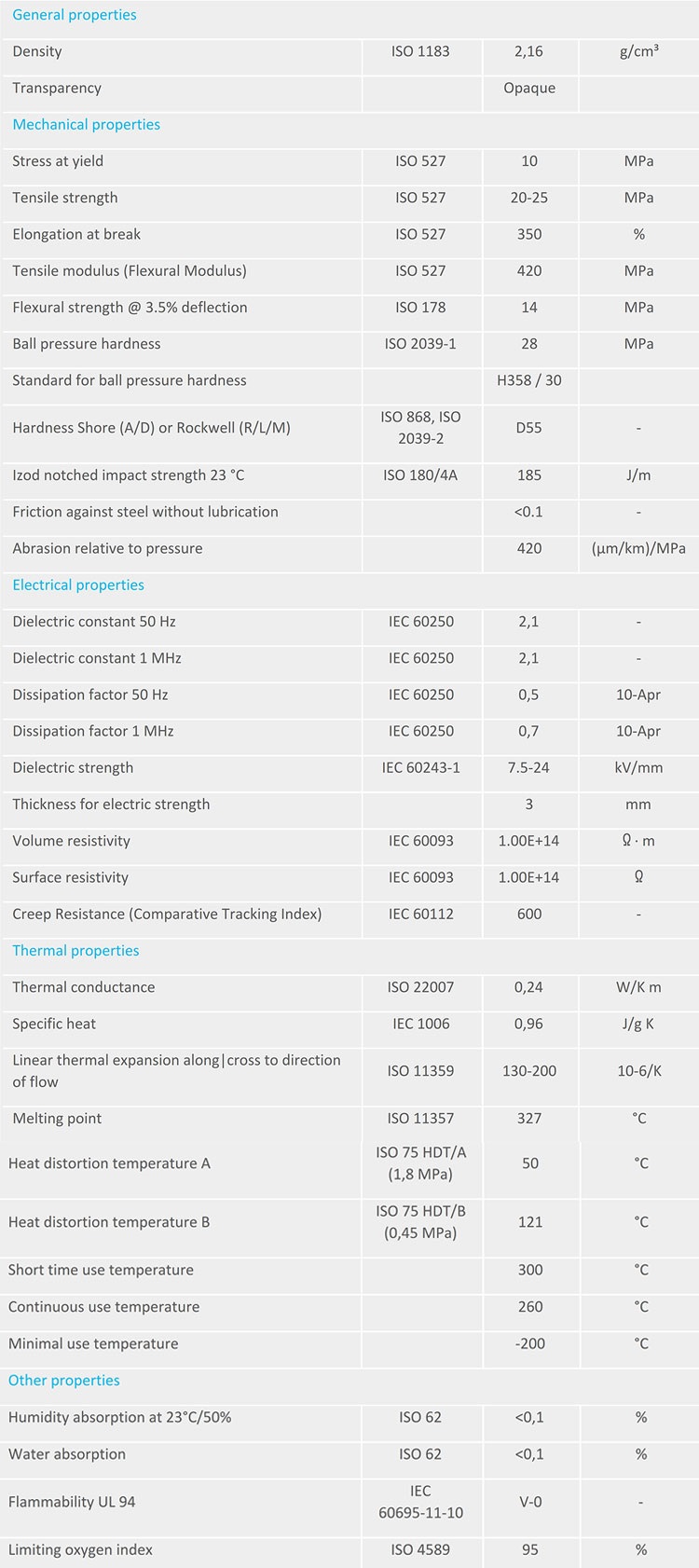
Properties of PolyTetraFluoroEthylene (PTFE) Thick-walled Tubes


Polymer Radomes (Radar Enclosures)

The evolution of radar technology over the past few decades has allowed it to be applied in multiple applications, even as the cost of the technology has reduced. In order to support the smooth functioning of radar antennae, radomes (quite literally, Radar-Domes) were developed to ensure that the antennae are kept free from interference – either environmental or wireless. The importance of the radome design cannot be stressed enough. In areas such as defense, it is imperative that the antennae are flawless. Missiles, for example, are guided using wireless communication and any interference that alters the missile’s trajectory could be catastrophic.

Still, considering that radar and wireless technologies can, by definition, pass through solids, there is a lot of design freedom on the radome’s material selection. However, certain radome materials do perform better and are therefore preferred.

Radome design

The cover of a sensor is critical of its construction and can have an important influence on sensitivity, radiated antenna pattern, and immunity to vibrations. Radome design involves minimizing microwave reflection at the surface of the cover. A poorly constructed radome can even cause unwanted sensitivity on the backside of the sensor. The cover material can also act as a lens and focus or disperse the radar waves. This is why it should have a constant thickness within the area used for transmission.

A radome should be designed in order to minimize its influence on sensor sensitivity as well as on the field pattern of the radar antenna. Any reflection caused by the radome leads to a degradation of the sensor characteristics. For FMCW radars, proper radome design is even more important than for simple Doppler Radars: reflections near the antenna cause strong feed through of the FM signal to the IF output.

An imperfect radome reflects parts of the transmitted waves. As a radome can never be perfect, relative movements (vibrations) between antenna and radome will lead to large signal levels at the radar transceiver. These signals mostly look like normal Doppler signals caused by moving targets and can lead to malfunction of the sensor system.

Materials used to construct radomes must be dry and electrically isolating. Any metallic parts – including coatings that may contain metals – must be avoided. Primarily, the following can be adhered to:

  • Radome cover must not be metallic

  • No plastic coating with colours containing metallic or carbon particles

  • The distance between cover and the front of Radar sensor >= 6.2mm

  • The optimal cover thickness is 3-4mm

  • Vibrations of the radar antenna relative to the cover should be avoided, because this generates signals that can trigger the output


Preferred materials for this application include the following:

Material

Permittivity (εr)

 Dissipation factor (tanδ)

Polycarbonate

 2.9

 0.012

ABS

 2.0-3.5

 0.0050-0.019

PEEK

 3.2

 0.0048

PTFE (Teflon®)

 2

 <0.0002

Plexiglass®

 2.6

 0.009

Glass

 5.75

 0.003

Ceramics

 9.8

 0.0005

PE

 2.3

 0.0003

PTFE Radomes

PTFE (Teflon®) is among the most effective materials available for radome construction. The material is fully machinable – implying that the uniform wall thickness required can be maintained throughout the part. In addition to this, PTFE is very robust in protecting against environmental forces over the long term. PTFE exhibits such low values for both permittivity and dissipation that it has virtually no effect on the antennae’s functioning.

Improvements in CNC machining – including CAM technology – have allowed increasingly complex radomes to be developed. These are usually made using high-purity virgin PTFE (Teflon®), which ensures that the values mentioned in the table above are attained without any hassle. Any impurities, discolorations or non-uniformity in the material would render it unsuitable for this application. Hence, care needs to be given that only the highest grade of resins are used in manufacturing the same.

Anti-Static PTFE Tapes

Among the myriad properties of PTFE that make it such a sought-after material, electrical resistance is one of the more popular. Because of its extraordinary dielectric strength and high breakdown voltage, PTFE is an invaluable addition in heavy electrical applications. As such, the following products are used across industries:

1. Skived PTFE tapes for heavy insulation 

2. Expanded PTFE (ePTFE) Tapes for cable wrapping

3. PTFE Radomes

4. PTFE transducer covers

5. PTFE insulation blocks

6. PTFE battery separators

These are but a few products that are commonly used. We often find that applications where electrical discharge is likely to be high benefit from a component made from PTFE to ensure that the equipment remains safe and does not leak current, causing harm.

Anti-static PTFE

The downside to the extreme insulative properties of PTFE lie in the build-up of static charge. Most applications do not find the build-up of static electricity to affect their process. However, certain assemblies – especially those where the equipment is being used in environments where flammability is high – require the charge to dissipate through the insulation so that sparks or static bursts do not occur. In such a situation, pure PTFE can cause problems, as it is such a strong insulator, that it does not allow the static charge to run through it.

To mitigate this problem, anti-static PTFE materials can be made, which employ conductive materials such as carbon to give mild conductive properties to the PTFE and allow it to discharge static build-ups through the carbon mixed into it.

Anti-static PTFE Tapes

Increasingly, applications that require PTFE tapes have started using anti-static tapes in areas where static build up can be an issue. However, most applications are very specific about the resistivity of the tape. Too much resistivity and you risk static build up; too little and you end up with a material that is too conductive to insulate effectively.

The base property of PTFE gives a surface resistivity of 10^14. For most conductive applications, this value needs to be reduced to 10^4. In order to achieve this, the base filler of carbon needs to be adjusted. A lot of this final property depends on both the base property of the virgin PTFE (different grades will vary from the base value mentioned above) and the conductive properties of the carbon additive itself. Various types of carbon will offer different levels of reduction in surface resistivity, implying the percentage of filler needs to be adjusted accordingly.

Another complication that arises due to the addition of carbon is that there can be a physical discharge of materials from the surface of the PTFE. Because PTFE and carbon are merely combined as a mixture, there is the likelihood that fine particles can come loose from the surface of the PTFE. For many high-purity applications, this can be a showstopper. Hence the quantity of the conductive filler needs to be minimized, while also allowing the conductive properties to be met. One material that has emerged as effective in this regard is Vulcan. While standard grades of conductive carbon need to be mixed to the extent of 10-15% into the PTFE (85% PTFE, 15% Carbon), with Vulcan, the same level of conductivity can be achieved with as little as 1-2%. However, as Vulcan is expensive, its incorporation is restricted to applications where there is a stringent need for no particle discharge to happen.

Electrical properties of pure virgin PTFE 

General properties

Density

ISO 1183

2,16

g/cm³

Transparency


Opaque


Mechanical properties

Stress at yield

ISO 527

10

MPa

Tensile strength

ISO 527

20-25

MPa

Elongation at break

ISO 527

350

%

Tensile modulus (Flexural Modulus)

ISO 527

420

MPa

Flexural strength @ 3.5% deflection

ISO 178

14

MPa

Ball pressure hardness

ISO 2039-1

28

MPa

The standard for ball pressure hardness


H358 / 30


Hardness Shore (A/D) or Rockwell (R/L/M)

ISO 868, ISO 2039-2

D55

-

Izod notched impact strength 23 °C

ISO 180/4A

185

J/m

Friction against steel without lubrication


<0.1

-

Abrasion relative to the pressure


420

(µm/km)/MPa

Electrical properties

Dielectric constant 50 Hz

IEC 60250

2,1

-

Dielectric constant 1 MHz

IEC 60250

2,1

-

Dissipation factor 50 Hz

IEC 60250

0,5

10-Apr

Dissipation factor 1 MHz

IEC 60250

0,7

10-Apr

Dielectric strength

IEC 60243-1

7.5-24

kV/mm

Thickness for electric strength


3

mm

Volume Resistivity

IEC 60093

1.00E+14

? · m

Surface resistivity

IEC 60093

1.00E+14

?

Creep Resistance (Comparative Tracking Index)

IEC 60112

600

-

Thermal properties

Thermal conductance

ISO 22007

0,24

W/K m

Specific heat

IEC 1006

0,96

J/g K

Linear thermal expansion along/cross to direction of flow

ISO 11359

130-200

10-6/K

Melting point

ISO 11357

327

°C

Heat distortion temperature A

ISO 75 HDT/A (1,8 MPa)

50

°C

Heat distortion temperature B

ISO 75 HDT/B (0,45 MPa)

121

°C

Short time use temperature


300

°C

Continuous use temperature


260

°C

Minimal use temperature


-200

°C

Other properties

Humidity absorption at 23°C/50%

ISO 62

<0,1

%

Water absorption

ISO 62

<0,1

%

Flammability UL 94

IEC 60695-11-10

V-0

-

Limiting oxygen index

ISO 4589

95

%