
The evolution of radar technology over the past few decades has allowed it to be applied in multiple applications, even as the cost of the technology has reduced. In order to support the smooth functioning of radar antennae, radomes (quite literally, Radar-Domes) were developed to ensure that the antennae are kept free from interference – either environmental or wireless. The importance of the radome design cannot be stressed enough. In areas such as defense, it is imperative that the antennae are flawless. Missiles, for example, are guided using wireless communication and any interference that alters the missile’s trajectory could be catastrophic.
Still, considering that radar and wireless technologies can, by definition, pass through solids, there is a lot of design freedom on the radome’s material selection. However, certain radome materials do perform better and are therefore preferred.
Radome design
The cover of a sensor is critical of its construction and can have an important influence on sensitivity, radiated antenna pattern, and immunity to vibrations. Radome design involves minimizing microwave reflection at the surface of the cover. A poorly constructed radome can even cause unwanted sensitivity on the backside of the sensor. The cover material can also act as a lens and focus or disperse the radar waves. This is why it should have a constant thickness within the area used for transmission.
A radome should be designed in order to minimize its influence on sensor sensitivity as well as on the field pattern of the radar antenna. Any reflection caused by the radome leads to a degradation of the sensor characteristics. For FMCW radars, proper radome design is even more important than for simple Doppler Radars: reflections near the antenna cause strong feed through of the FM signal to the IF output.
An imperfect radome reflects parts of the transmitted waves. As a radome can never be perfect, relative movements (vibrations) between antenna and radome will lead to large signal levels at the radar transceiver. These signals mostly look like normal Doppler signals caused by moving targets and can lead to malfunction of the sensor system.
Materials used to construct radomes must be dry and electrically isolating. Any metallic parts – including coatings that may contain metals – must be avoided. Primarily, the following can be adhered to:
-
Radome cover must not be metallic
-
No plastic coating with colours containing metallic or carbon particles
-
The distance between cover and the front of Radar sensor >= 6.2mm
-
The optimal cover thickness is 3-4mm
-
Vibrations of the radar antenna relative to the cover should be avoided, because this generates signals that can trigger the output
Preferred materials for this application include the following:
|
Material |
Permittivity (εr) |
Dissipation factor (tanδ) |
|
Polycarbonate |
2.9 |
0.012 |
|
ABS |
2.0-3.5 |
0.0050-0.019 |
|
PEEK |
3.2 |
0.0048 |
|
PTFE (Teflon®) |
2 |
<0.0002 |
|
Plexiglass® |
2.6 |
0.009 |
|
Glass |
5.75 |
0.003 |
|
Ceramics |
9.8 |
0.0005 |
|
PE |
2.3 |
0.0003 |
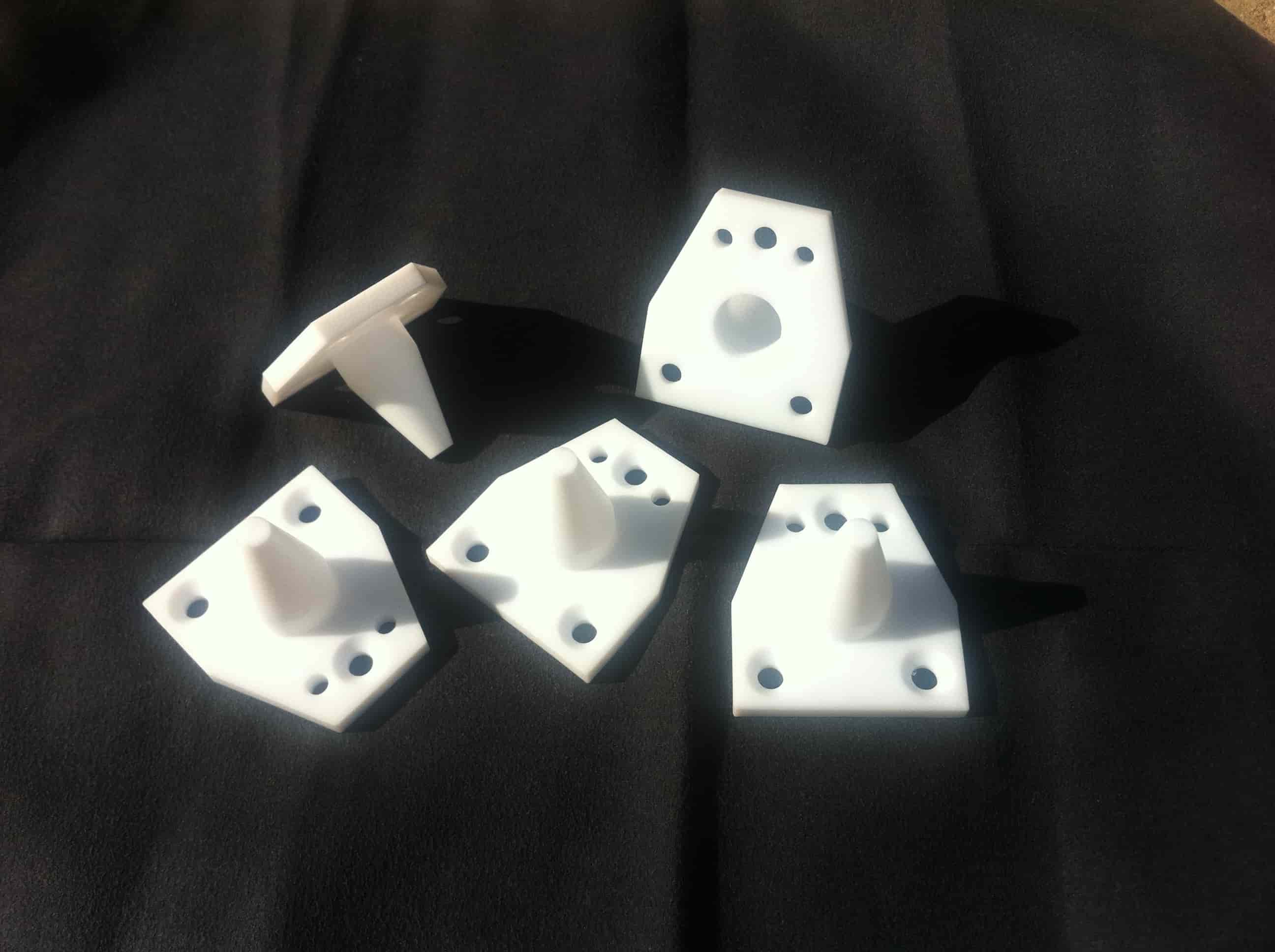
PTFE Radomes
PTFE (Teflon®) is among the most effective materials available for radome construction. The material is fully machinable – implying that the uniform wall thickness required can be maintained throughout the part. In addition to this, PTFE is very robust in protecting against environmental forces over the long term. PTFE exhibits such low values for both permittivity and dissipation that it has virtually no effect on the antennae’s functioning.
Improvements in CNC machining – including CAM technology – have allowed increasingly complex radomes to be developed. These are usually made using high-purity virgin PTFE (Teflon®), which ensures that the values mentioned in the table above are attained without any hassle. Any impurities, discolorations or non-uniformity in the material would render it unsuitable for this application. Hence, care needs to be given that only the highest grade of resins are used in manufacturing the same.

