Unravelling Polymers

The Definitive Blog on Polymers by Poly Fluoro Ltd.

Solar Tracker Bearings - Considerations for Design and Manufacture

With renewable energy showing no signs of slowing down, it has become of paramount importance to understand and adapt to the growing needs of this industry. The increase in outlay, combined with the aggressive targets that these projects set make it essential to have quick, ready solutions that are both scalable and replicable across projects.

Solar power plants – as we covered in an earlier article – are still on a path towards maximising efficiency. While it is true that some plants can now boast costs per unit below that of traditional power plants, this does not hold true across the industry. Furthermore, it is well known that without subsidies, many of these plants would not have been able to sustain themselves up to the point where they were no longer losing money operationally.

As one might imagine, solar plants are highly dependent on the extent to which they can maximise the exposure of their panels to the sun. It is not alone enough to have an ample quantum of sunlight. Without the panels at the right angles, the ‘harvest’ from the sun’s energy will remain low and the plant may not achieve the efficiencies needed to justify its operational viability.

We covered Solar Tracker Bearings in an earlier article, where we looked mainly at the composition of the material used. Since then, we have had the chance to explore both the design elements and manufacturing challenges that arise in this product. In addition to this, experience is showing us that the global industry is focussed on a few key sizes and developing these are the key to having a ready solution.

Load and stress considerations

The fundamental purpose of the solar tracker bearing is to bear the load of the square pipe on which the panels are fixed. This pipe is rotated by the solar tracker mechanism itself and the bearing also facilitates this rotation. The pipes are usually found in 90mm, 100mm, 120mm and 150mm sizes and these appear to be a standard across the industry.

Loads experienced by the bearing are typically vertical loads – the weight of the pipe – and radial loads as the bearings rotate while in contact with the clamps around them. It is therefore required to have bearings that can absorb this vertical load while having a low enough coefficient of friction to allow for smooth rotation.

Vertical loads could be in the range of 10-15KN (1-1.5 Tonnes). While this is a relatively low load, it is still vital to check that the bearing can accommodate it, before committing to the client.


We used 3D simulations of the assembly on our design of the bearing to check the stress points and displacements on the bearing. This is a part that would need to work over many years outdoors, so we needed to be sure it would not buckle under the loads. Our stress checks confirmed that given the loads we had defined, the part would experience a deflection of within 60 microns, which is well within the acceptable limits.
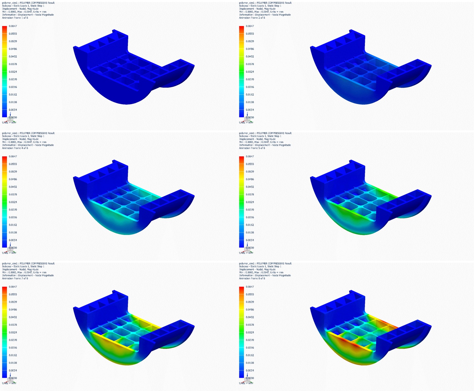


Part design considerations

As we covered before – one of the main criteria for the bearing is that it needs to be light-weight. The bearing weight feeds back into the efficiency of the solar plant. Heavier bearings imply a higher load on the solar tracker when it rotates the pipe. This in turns means a higher power consumption and a net energy loss to the system.

Keeping the bearings light-weight mean that the parts benefit from being injection moulded, not machined. Although we do have projects where we have supplied machined bearings, these are usually for trials and fitment. Once the bearings are needed in bulk, injection moulding not only allows for higher volumes, but also allows for designs such as the one we have shown above, ensuring a 60-70% weight (and therefore cost) saving over a machined part.

The mould for a given bearing would have a life of nearly 200-300K sets. Considering a single project requires anywhere between 20K and 30K sets, it is possible to develop a mould and use it over many projects.

In our experience, if the volume requirement exceeds 5K sets, it is more cost effective to develop a mould, rather than opt for the parts to be machined.

Material design considerations

We covered material composition in our earlier article. However, it is important to reiterate that the materials to be used must have the following properties:

  1. Light weight

  2. Low moisture absorption

  3. UV resistant

  4. High strength

  5. Low coefficient of friction

  6. Wear resistant

  7. Injection mouldable

Special formulations exist that offer the above properties. Being in control of the formulation allows the recipes to be tweaked based on a client’s requirements.

There is still much to learn about the solar tracker field, but with each project, our understanding and familiarity improves.

PEEK - Robust Enough for Nuclear Applications

Among the most rigours manmade environments ever created, the inside of a nuclear reactor would probably rate high on the list. The process that allows the reactor to generate the kind of energy we need is not only complex in theory but poses huge practical hurdles when it comes to containment and durability.

Apart from the energy release, nuclear reactions also give off radiation – most notably gamma radiation – which most standard materials are unable to withstand. Gamma radiation causes other materials to get ionised, which in turn makes them hazardous for human exposure. It also accelerates the degradation of materials, causing brittleness and fractures that can increase the likelihood of leaks and failures.

PEEK has long been known as a polymer with unparalleled strength. We have compared earlier the tensile strengths, tensile modulus, heat resistance and chemical resistance of PEEK. In addition to this, the material can reach strengths comparable with metals, when used with the right kinds of fillers. Adding to this list is the capability of PEEK to dwell within high-radiation environments without suffering any significant losses in properties.

Studies have shown that when exposed to the harsh environments seen within the nuclear reactor chamber, PEEK is able to survive over an extended period, where other materials would easily fail. Most notably, the effect of gamma radiation on PEEK is low, meaning that PEEK becomes the material of choice for a host of applications within the nuclear reactor.

  1. PEEK Seals
    The performance of seals to contain liquids that flow within the reactor is of utmost importance. Most materials would suffer from brittleness and deformation when subjected to radiation and heat from this system. PEEK seals have been shown to hold their shape over time and tests show that the hardness and crystallinity of the material is not severely affected by the conditions.

  2. PEEK linings
    Vats and chambers within the nuclear reactor have relied traditionally on using linings made from heavy metals such as lead and titanium. This is both expensive and makes the process of holding and disposing of nuclear waster very cumbersome. PEEK linings have been shown to be very effective in containing radiation. It is possible to make thinner walled tanks and have them lined or coated with a thin layer of PEEK.

  3. PEEK Valves, Plates and Nozzles
    Given the quantum of fluids within the reactor, PEEK is now replacing many of the standard valves, plates and nozzles to ensure that key components within the system do not fail. PEEK is both highly machinable and injection mouldable. Further, PEEK can be 3D printed to create specialised shapes that fit perfectly within an existing system. This versatility lends itself both to precision components needed within the system during construction of the nuclear reactor as well as specialised parts that may be required for maintenance, reinforcement and/or damage control once the reactor is already operational.

As the field expands, new applications of PEEK within the nuclear space are constantly being discovered. Given we know that PEEK is able to survive within the environment without suffering adversely, it remains to be see where else this polymer will find uses.

Identifying Virgin Plastics

What is virgin plastic?
Put simply, it is a polymer in its pure form. Many polymers - such as PTFE, PEEK and Nylons - are used by adding a filler such as glass or carbon to enhance the material properties. In virgin plastic, no fillers have been added.

Despite ample data on the properties of various polymers, it is easy to understand that most end-users rely on the word of the supplier that the polymer they are paying for is the polymer they are getting.

Because many of the properties are inherently difficult to test, one would need to send the material to a lab for identification. And because the methods of identification are sometimes complex and require many types of tests, this can end up being an expensive affair. A client may be willing to undertake this expense one time, but if a component is supplied regularly, it would be cumbersome to test the materials each time a new lot is received. Hence, for the most part, clients accept the material test certificates (MTC) as provided by the supplier and trust that the parts supplied are from the lot corresponding with the MTC.

In our own experience, we have come across many instances of clients claiming they are using a certain polymer when in reality, the material they are being supplied is a cheaper variant of the polymer they think they are using.

A few examples of these are highlighted in the table below:

Polymer Substitute Price difference
PEEK PEK, PAEK 2X
PTFE Polypropylene, Polyethylene 4-5X
UHMWPE LDPE, HDPE 2-3X
PCTFE PTFE, Polypropylene 10-20X
FEP Polypropylene, Polyethylene 40-50X
PA66 PA6 1.5-2X
PFA Polypropylene, Polyethylene 40-50X

In most cases, the criteria for this substitution is clearly price. We receive many samples from potential clients claiming to be either PEEK or PTFE. In some cases, a lab test is not even needed as it is visually obvious they are using another polymer.

In a few cases, the non-availability or the non-processability of the polymer leads to suppliers opting for substitutes. For example, the inability of UHMWPE to be easily injection moulded leads some processors to use LDPE or HDPE instead. Visually, it is difficult to tell these polymers apart, so the client accepts the alternate material without question.

Obviously, the performance of these materials cannot match up to the polymer originally chosen for the application.

In one case, we received samples from a client claiming they were PEEK and enquiring as to why they should have failed in his application. The part was a ball valve seat, procured from another vendor and had deformed after only a few months of performance. When we explained that the part was PEK, the client insisted that his supplier was giving him PEEK. When the part was sent to the lab and it was confirmed that the part was PEK, the client asked us to supply him the same part, but with virgin PEEK. When we explained that the price would be nearly double, they refused to accept, asking us to match the price they were already getting. Eventually, they returned to their original supplier, even though they knew the material being supplied was inferior. The commercial impact of using virgin PEEK was too high for them and they preferred using the cheaper variant and dealing with the rejections that came with this.

In an attempt to make the identification of certain polymers more transparent, we created the above infographic. Using this, basic tests can be performed to ensure that the polymer is as committed.