Unravelling Polymers

The Definitive Blog on Polymers by Poly Fluoro Ltd.

Optimizing Solar Tracker Bearings for Enhanced Solar Energy Harvesting

In the pursuit of sustainable energy sources, solar power stands out as a prominent solution for mitigating the environmental impact of traditional energy generation methods. While wind and hydroelectric energy are no doubt gaining traction, solar power remains our most abundant source of energy. Harvesting this efficiently is the key to moving into a phase where fossil fuels are no longer vital to the survival of industry. 

Solar trackers play a crucial role in maximizing the efficiency of solar panels by ensuring they follow the sun's trajectory throughout the day. This is especially needed in countries further away from the equator, where the angle of the sun changes more dramatically with seasons and where the intensity of the sunlight is weak and therefore needs to be harvested more effectively.

At the heart of these solar trackers are specialized components known as bearings, which enable smooth and precise movement, and which reduce the friction of the system, allowing for less energy consumption. This article delves into the significance of solar tracker bearings, their types, and the advancements in bearing technology that contribute to the optimization of solar energy harvesting.

The Basics of Solar Tracker Bearings:

Solar trackers are devices that orient solar panels to face the sun, maximizing the amount of sunlight they receive and, consequently, the energy they generate. Bearings are fundamental components of solar trackers, facilitating the movement of the tracking system. The primary purpose of these bearings is to enable the solar panels to follow the sun's path from sunrise to sunset, ensuring they are always positioned at an optimal angle to capture sunlight.

Ultimately, solar energy is a weak source when compared with non-renewable sources. Hence, the power that is generated by a solar plant needs to exceed the power used to run the plant if the project is expected to be viable. Building efficiencies into the system minimise the energy consumption. Low friction solar tracker bearings that allow easy movement  of the solar panels are therefore crucial.

Types of Solar Tracker Bearings:

Azimuth Bearings:

Azimuth bearings enable horizontal rotation of the solar tracker, allowing it to follow the sun's east-west movement. These bearings play a pivotal role in ensuring that solar panels are oriented correctly throughout the day.

Elevation Bearings:

Elevation bearings, on the other hand, facilitate the vertical movement of solar trackers, ensuring that panels can track the sun's movement on its daily arc. These bearings are critical for adjusting the tilt angle of the solar panels based on the sun's position in the sky.

Polar Bearings:

Polar bearings are responsible for the rotational movement of the solar tracker around the polar axis. This rotation is essential for tracking the sun's seasonal variations, accommodating changes in its elevation angle throughout the year.

Advancements in Solar Tracker Bearing Technology:

With the advancements in polymer technology, the option now exists to make bearings that withstand high loads, offer low friction with minimal lubrication, and are highly cost effective against metal bearings.

Experimenting with different formulations that optimise all elements of the solar tracker bearing’s functions yields certain elements that are essential in building an effective bearing solution. These include:

  1. 3D modelling to create an efficient, low-weight lattice structure that can accommodate the required radial loads of 1.5-2 Tonnes. Lower weight also means the bearings are far more cost effective 

  2. The incorporation of friction reducing additives that, if blended properly, will allow the bearings to smoothly function with no external lubrication. Early bearings manufactured from plain polymers were working will in the summer. But once winter set in, loud squeaking sounds could be heard as the tracker rotated the panels. A new friction-reducing formulation erased this issue completely

  3. The addition of UV protection additives that ensure that 99.9% of ultraviolet radiation does not penetrate below 0.1mm of the bearing surface. This has allowed our bearings to undergo 100-year tests and suffer no observable polymer degradation at the end

  4. The development of housing using complementary polymers that offer the lowest coefficient of friction against the bearing.

The benefits of Solar Tracker Bearings made with these factors considered are many

  1. Maintenance-Free - Traditional bearings may require regular maintenance to ensure optimal performance, but advancements in bearing technology have led to the development of maintenance-free bearings. These bearings, often sealed or lubricated for life, reduce the need for frequent inspections and maintenance, contributing to the overall reliability of solar tracker systems.

  2. High Precision and Accuracy - Precision and accuracy are crucial factors in solar tracking systems. Modern bearings are designed with enhanced precision, minimizing tracking errors and ensuring that solar panels consistently align with the sun. This increased accuracy results in higher energy yields from solar installations.

  3. Durability in Harsh Environments - Solar trackers are deployed in outdoor environments where they are exposed to varying weather conditions. Advanced bearing formulations are engineered to withstand harsh environmental factors such as extreme temperatures, humidity, UV, and other corrosive elements, ensuring long-term durability and performance.

  4. Low FrictionSolar Tracker Bearings are designed to minimize energy losses during the rotation of the solar trackers. By reducing friction, these bearings enhance the overall efficiency of the tracking system, allowing solar panels to smoothly follow the sun's movement with minimal energy consumption.

  5. Dual-Axis Tracking Systems - While single-axis tracking systems follow either the horizontal or vertical movement of the sun, dual-axis tracking systems incorporate both azimuth and elevation tracking. Bearings in dual-axis systems are specially designed to facilitate complex movements, ensuring precise alignment with the sun at all times. This results in even greater energy capture efficiency, especially in locations with high solar irradiance.

Conclusion:

The capability to design the bearings, create a precise formulation of the polymer based on the environment of use, and mould or even machine the bearings and housings as needed is what sets apart companies looking to engineer bearings rather than simply mould them from a template. This all-round capability allows us to treat each project as unique and develop a solution that effectively targets the customer’s needs and boosts the overall efficiency of the project.

It is likely that as the industry matures, the bearing technology too will evolve. Nonetheless, we expect to be at the forefront of this product that is at the heart of the green energy revolution.


Read More

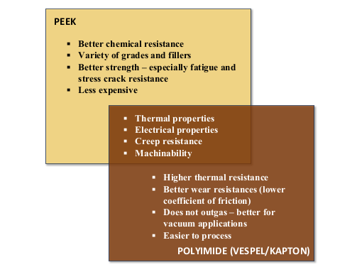
1. PEEK Vs Polyimide - Comparing Two of the Toughest Polymers

2. PTFE Extrusion - Ram vs Paste Extruded - A comparison of features

3. Exploring the Versatile World of PVDF

PEEK Vs Polyimide - Comparing Two of the Toughest Polymers

In the realm of high-performance polymers, PEEK (Polyether Ether Ketone) and Polyimide stand out as two exceptional materials. Both are undoubtably among the toughest polymers, exhibiting tensile and flexural strengths far higher than even their nearest competitors. Given this, it is easy to see them as substitutes for one another and for an engineer to be confused over which one to choose in a given application. 

Comparing chemical structure:

PEEK is a semi-crystalline thermoplastic known for its excellent mechanical properties, chemical resistance, and high-temperature stability. Its molecular structure imparts exceptional resistance to chemicals, abrasion, and wear. 

On the other hand, Polyimide (often known by its brand names of Vespel or Kapton) is a high-performance polymer with a unique imide linkage in its molecular structure. This arrangement contributes to outstanding thermal stability, excellent dielectric properties, and exceptional resistance to radiation and chemicals. 

Mechanical Properties:

When it comes to mechanical properties, PEEK and polyimide both display distinct characteristics. PEEK offers a combination of high strength, stiffness, and toughness. Its tensile strength and modulus are comparable to some metals, making it a preferred choice in structural applications where mechanical integrity is crucial. PEEK's inherent toughness allows it to withstand repeated loading and impact without sacrificing performance. PEEK can also be enhanced with the addition of Glass, Carbon, and Graphite (Carbon-Graphite reinforced PEEK, also called HPV PEEK, is among the toughest polymer compounds known), which adds to PEEK’s versatility.

Polyimide, while not as stiff as PEEK, excels in maintaining its mechanical properties at elevated temperatures. Its ability to withstand prolonged exposure to high temperatures without significant degradation makes polyimide suitable for aerospace, electronics, and automotive applications where a combination of thermal stability at elevated loads is paramount.

When it comes to wear resistance, polyimide take the edge, as it exhibits a slightly lower coefficient of friction. While PEEK can be improved with the addition of PTFE, the base wear rate of polyimide is both low and constant over a range of loads. This means that in dry-running applications it is a better choice.

Thermal Stability:

Thermal stability is a key consideration in many high-performance applications, and both PEEK and polyimide offer exceptional heat resistance. PEEK is known for its thermal stability up to 260°C, making it suitable for applications in aerospace, automotive, and oil and gas industries. However, polyimide surpasses PEEK in terms of thermal stability, with some formulations capable of withstanding temperatures exceeding 300°C. This makes Polyimide the material of choice in extreme temperature environments such as electronics and aerospace applications.

PEEK boasts a high glass transition temperature (Tg) of around 143°C, making it suitable for applications in demanding thermal environments. However, polyimides typically exhibit a higher glass transition temperature than PEEK, often exceeding 250°C, making them more ideal for applications demanding extreme temperature resistance.

Chemical Resistance:

Chemical resistance is another critical factor in material selection, especially in harsh operating conditions. PEEK exhibits excellent resistance to a wide range of chemicals, including acids, bases, and hydrocarbons. It is also biocompatible. This makes it a preferred choice in chemical processing, medical, and oil and gas applications. Polyimide, with its unique molecular structure, provides outstanding chemical resistance, particularly against solvents, acids, and radiation. This property makes Polyimide suitable for applications in the aerospace, electronics, and semiconductor industries.

Cost and processing considerations

When it comes to cost, however, there is little need to compare the two. Polyimide’s key drawback is that it is prohibitively expensive. Polyimide is roughly 3-4X the cost of PEEK, which is significant considering that PEEK itself is about 20-25X the cost of more basic polymers such as POM or Nylons. Hence, most parts made from polyimides tend to be smaller and used sparingly in applications where PEEK does not make the cut.

Processing-wise, the other drawback of polyimide is that it cannot be injection moulded. It can only be compression moulded or extruded as a rod. This limits the complexity of parts that can be made when compared with PEEK. However, when we speak of compression moulding specifically, polyimide is more versatile and comparatively easier to process. While PEEK only lends itself to hot compression moulding (where the pressure and temperatures must act simultaneously), polyimide can also be cold compression moulded in a manner similar to PTFE. This allows for a much higher productivity, wherein material can be compressed and placed in an oven in batches, rather than moulded one at a time the way PEEK needs to be.

Conclusion

While it is fair to compare PEEK and Polyimide, the key consideration of cost means that PEEK usually wins out. However, there are certain applications where only Polyimide can be used and where cost may not be the biggest concern. It is likely that as polyimide gets cheaper (as polymers invariably do over time), the use cases will rise, and PEEK will have a worthy competitor.


Read More

1. PTFE Extrusion - Ram vs Paste Extruded - A comparison of features

2. Exploring the Versatile World of PVDF

3. Air Permeability Testing and Water Entry Pressure Testing in Expanded PTFE Membranes

Case Study - PVDF Compression Moulding

The versatility of PVDF as an engineering plastic is well known. Indeed, we have covered the advantages, properties, and applications of PVDF in an earlier article. Properties such as extreme chemical resistance, UV resistance, thermal stability, and piezoelectricity all make PVDF an intriguing polymer that finds application across a host of different industries.

Our own experience with PVDF has thus far stayed within the realm of machining. PVDF rods and sheets are available and can be easily machined to make a final component. The polymer itself throws up no surprises with regards to how it behaves dimensionally, post-machining.

Recently, however, we have encountered a challenging prospect. The part we were asked to develop was far too large to be machined from a rod or a sheet. With an outer diameter of about 200mm and an inner diameter of 130mm, the part would have caused far too much waste were it to be cut from a sheet or a rod. The option, therefore, would be to compression mould it.

Given our expertise in PTFE and PEEK moulding, we assumed that PVDF – whose melting temperature is far less than either PTFE or PEEK – would be simple enough to mould.  We knew from discussions with our suppliers that the equipment we use for PEEK moulding could be easily used for PVDF, provided the processing parameters were adjusted accordingly.

Our first experience with the moulding convinced us that this was a fairly simple affair. We moulded a small rod of 100mm diameter and 50mm thickness and found the part to be uniformly coloured (PVDF should be milky white), with no signs of any blowholes. Skived sections taken from the rod confirmed that the tensile properties were in line with what was expected, while the specific gravity was also in the range of 1.8, as it should have been.

Moving from the test sample to the part we needed to mould showed us that we may have underestimated the material. A few challenges were immediately apparent:

  1. The material was extremely sensitive to temperature. While the 100mm sample appeared to have formed easily under a temperature of 210°C, the larger part was getting discoloured and turning brown.

  2. The melt flow of the material was challenging to control. If the temperature was held for too long, the viscosity of the material would reduce and cause it to leak from the mould. If the temperature was not held long enough, the part would come out with blowholes, having not been sufficiently melted throughout.

  3. Similarly, too much pressure would cause material leakage, while too little pressure would not allow all the air to be expelled, resulting in blowholes.

In effect, moulding PVDF turned into a very precise give and take between temperature, dwell time, and pressure. Furthermore, although the material could be re-melted, doing so would discolour the polymer, rendering it useless. This meant that all parameters needed to be precise and that a cycle could be run only once else the material would be lost. (Incidentally, we are not new to this conundrum. PTFE behaves in much the same way, only we have decades of experience with PTFE and know how to get it right every time!).

Once we had moulded the part, the time came to machining it. Again, although our experience with machining PVDF had always been smooth, here too we observed that compression moulded PVDF behaves slightly differently post machining. Stresses in the material tend to relax overnight, causing slight deviations in dimension. Hence, adjustments needed to be made to the machining process to allow for the same.

There is a reason that engineering polymers are a niche space and that so few have the expertise to consistently manufacture certain high-performance plastics. We pride ourselves in being able to understand our polymers and to investing the time it takes to develop them.


Read More

1. Case Study - PEEK in Coffee Machines

2. Polymers in Low Friction Applications

3. PTFE Extrusion - Ram vs Paste Extruded - A comparison of features