Unravelling Polymers

The Definitive Blog on Polymers by Poly Fluoro Ltd.

Polymers in Renewables - The Rising Role of High-Performance Plastics in Renewable Energy

As the world takes a conscious and collective stand against the rising use of fossil fuels, it also disrupts a status quo set in place during the dawn of the industrial revolution. Since fossil fuels began to power our homes, factories and cars, most technological developments have focussed merely on efficiency gains. The improved productivity of coal-fired power plants, combined with better refining techniques and higher efficiency engines have allowed us to do more with less. At the same time, demand has moved steadily upwards, implying that even with these productivity gains, costs have always been rising.

The biggest hurdle to renewable energy was always the fixed costs involved. Consider a solar, or wind-powered plant. Not only is there no option to run these plants 24x7, but the cost per unit of power produced, when added to the cost of the infrastructure itself, always lagged the numbers showcased by their traditional, fossil fuel counterparts. However, efficiency gains have been made in renewables as well. In fact, one might argue that while we have somewhat plateaued with the gains in fossil fuel productivity, the gains in renewables are only just getting started. As a result, the earliest solar plants are now starting to show net positive gains when compared with coal power plants. The same can be said for wind and hydroelectric power plants.

Assisting in this wave of continual improvements in efficiency and productivity are polymer materials that lend their properties to this endeavor. Here we look at a few ways in which high-performance polymers are contributing to the field of renewable energy.

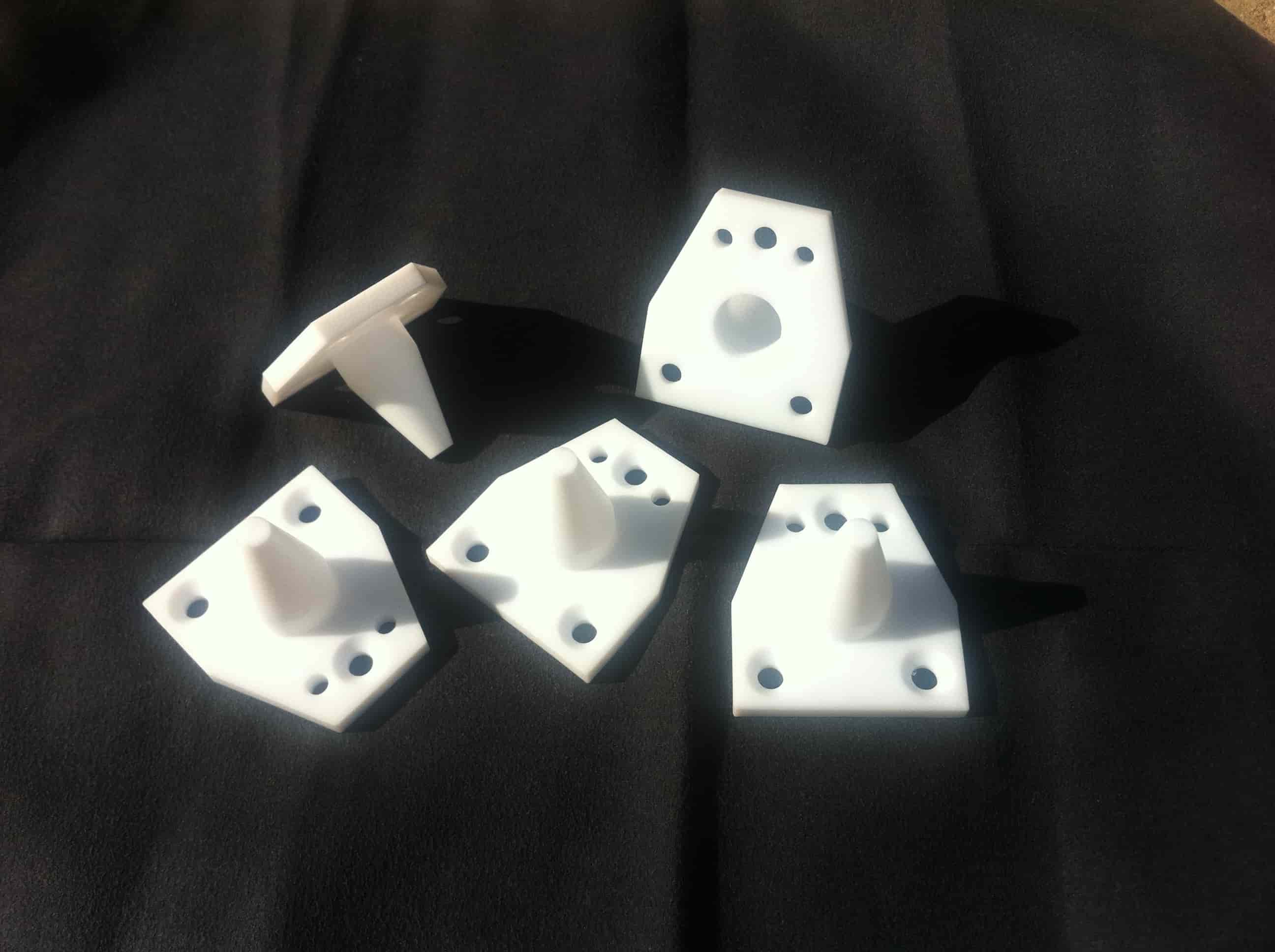
1. Solar Tracker Bearings

The effectiveness of a solar panel in maximizing the energy it can harvest is improved by ensuring it receives the highest intensity of sunlight possible. Solar tracker systems are designed to rotate the solar panels in order to keep them facing the sun at an optimal angle. However, the energy expended in rotating the panels cannot exceed the efficiency gains from the rotation itself. Thus, it is critical to have a low-cost, low-friction process that limits the energy consumption of the tracker.

Solar tracker bearings are made using high-performance, UV resistant polymers that are both light-weight, low in cost and easy to install. In addition to this, we have developed solar tracker bearings that employ fiction reducing additives, leading to higher efficiency gains in the system. Cost-wise, the bearing assembly can be made at roughly 1/10th the cost of a traditional metallic bearing. 

solar tracker bearings

2. Bearings for wind turbines

Like solar tracker systems, wind turbines too have a tracking system which maximizes the angle of the turbine to ensure it receives the most energy. In addition to this, the process of harnessing wind energy is a rotary process, implying higher RPMs and a need for lower friction. Any friction in the system immediately results in a net energy loss. Hence, high-performance polymers such as PTFE find use in these applications. Although PTFE can be an expensive material, the coefficient of friction it offers can be as low as 0.03 when moving against polished stainless steel. This allows a simple PTFE bearing to take on loads and prove effective in applications where otherwise heavy and more expensive metal assemblies would be needed. Furthermore, as PTFE is a self-lubricating material, the need for grease and/or constant maintenance is significantly reduced. This is especially useful for wind turbines, which are usually located in remote areas and benefit from needing less maintenance.

3. EV charging stations

Electric Vehicles are gaining traction over traditional fuel powered vehicles. As their demand and prevalence grows, so too would the infrastructure needed to ensure that they can function smoothly. Investments in EV charging stations have increased significantly and new housing developments are increasingly required to ensure that there are charging stations for all parking slots.

As a superior insulation material, PTFE has been found effective in EV charging stations. PTFE insulation blocks can be used to improve the charging efficiency and ensure that there is minimal leakage of current.

4. Battery separators
One of the key factors with renewable energy is that storage needs to be both ample and efficient. While traditional power plants feed directly into the grid, solar and wind plants will only generate power in bursts. As a result, a lot of effort has gone into battery technologies. Both PTFE and PE (polyethylene) are seen as effective battery separators.

These separators provide internal insulation to the battery, preventing the batteries from discharging when idle. Although PE separators are effective in most applications, high-voltage applications need PTFE films, which possess higher breakdown voltage strengths and can remain effective over a much longer time period. These PTFE films can be made in thicknesses of as low as 40 microns and have breakdown voltages of as high as 100KV per mm.

5. Plastic to diesel conversion - renewable polymer fuels

While polymers are certainly effective in improving the efficiency of renewable energy systems, the irony is that most polymers are manufactured from fossil fuels themselves. However, recent advancements in plastic-to-fuel technologies have allowed waste polymers to be converted back into combustible fuels. While this does not exactly fall in the same category as renewables, it does allow for a lot of waste plastics to be re-used, rather than end up in landfills.

The above are but a few applications where polymers are finding use. In truth, there are myriad different areas when the properties of high-performance plastics can be utilized to improve, enhance and augment existing systems of renewable energy.

PTFE Thick-walled Tubes - Applications & Manufacturing Challenges

The use of PTFE tubes has become quite widespread across industries. As the scale of manufacture of regular thin-walled PTFE tubes has expanded, the cost has become less prohibitive. As a result, applications that were sensitive to the price of PTFE tubes have been able to adopt them.

In truth the properties exhibited by these thin-walled tubes are so diverse, that there is nearly no application where it cannot enhance the efficiency of a system. We have looked before at the overall properties of PTFE tubes and its application across various industries. However, we want to explore further the properties and challenges of thick-walled PTFE tubes.

Challenges in making thick-walled PTFE tubes

PTFE is a material that is challenging to process. Standard moulding processes that can be applied to what we call ‘melt processable plastics’ do not apply. Since PTFE does not melt, it cannot be converted into a liquid form and passed through a die. Instead, other methods are employed to achieve the shapes and profiles needed.

The processes for making PTFE tubes include:

  1. Paste extrusion – where the PTFE powder is mixed with an extrusion aid to form a ‘paste’ and this is passed through an extrusion die at high pressure to attain the shape

  2. Ram extrusion – where powder is added in successive charges into a die and a ram keeps compacting the powder such that a continuous profile is achieved

  3. Compression moulding – where small profiles can be made (usually less that 1000mm in length) by simply compacting the PTFE powder within a die.

Both ram extrusion and compression moulding are employed when the diameters of the tube are in excess of 1” and when the final length needed does not exceed 2-3 meters. In case we want long lengths of tube, paste extrusion is the only option.

The length of a paste extruded tube is limited by the amount of powder that can be loaded into the extruder, since there is no option to add more powder once the extrusion begins. Most extruders would have a maximum capacity of about 10Kgs. Depending on the size of the thick-walled tube itself, the final length will be determined.

For the most part, paste extruded tubes are used to make thin-walled tubing, which is tubing where the wall thickness is within 2mm. The process for making thin-walled tubes follows a continuous sintering process, wherein the tube is extruded directly into the heating ovens and cured at the same rate at which it is extruded. This facilitates the need for a high structure to house the extrusion equipment. Typically, the extruder sits on the topmost floor, a drying oven on the floor below it and a sintering oven under the drying oven. Temperatures are set such that the drying oven is able to remove all traces of the extrusion aid (which is flammable) before the extruded tube reaches the sintering oven.

For higher wall thicknesses, there remain certain hurdles for paste extrusion in this manner. While extrusion itself is not a problem, the thick-walled tube is much tougher to sinter. The quantum of extrusion aid is high, owing to the high cross section of the tube. Hence, ensuring all removal of the extrusion aid in the drying oven is not guaranteed. This can result in fire when the tube reaches the sintering oven, where temperatures would be much higher than the flash point of the extrusion aid.

The other problem with thick-walled tubing is the weight of the tube itself. As thin-walled tubes are light, they place very little load on themselves during sintering, where the tube is soft. In contrast, the load of the thick-walled tube can result in it pulling on itself while in a heated state, causing stretching or deformation in the dimensions. 

For this reason, separate sintering cycles and processes need to be developed for thick-walled tubing. Our own experience has shown that the drying and curing cycles need to be fine tuned to ensure that the tube remains uniform in dimension and does not crack or split during sintering.

Applications for thick-walled PTFE tube

Thick-walled PTFE tubes are used in areas where high burst pressures or high voltages exist. These applications include:

  1. Pantographs for the railways

  2. Insulation liners for heavy electricals

  3. High-pressure pneumatic lines

  4. Liners for high-wear applications

  5. Shields for chemical equipment

The strength and insulative properties of PTFE ensure that it is often the only material of choice in applications involving strenuous environments.

Properties of PolyTetraFluoroEthylene (PTFE) Thick-walled Tubes


Polymer Radomes (Radar Enclosures)

The evolution of radar technology over the past few decades has allowed it to be applied in multiple applications, even as the cost of the technology has reduced. In order to support the smooth functioning of radar antennae, radomes (quite literally, Radar-Domes) were developed to ensure that the antennae are kept free from interference – either environmental or wireless. The importance of the radome design cannot be stressed enough. In areas such as defense, it is imperative that the antennae are flawless. Missiles, for example, are guided using wireless communication and any interference that alters the missile’s trajectory could be catastrophic.

Still, considering that radar and wireless technologies can, by definition, pass through solids, there is a lot of design freedom on the radome’s material selection. However, certain radome materials do perform better and are therefore preferred.

Radome design

The cover of a sensor is critical of its construction and can have an important influence on sensitivity, radiated antenna pattern, and immunity to vibrations. Radome design involves minimizing microwave reflection at the surface of the cover. A poorly constructed radome can even cause unwanted sensitivity on the backside of the sensor. The cover material can also act as a lens and focus or disperse the radar waves. This is why it should have a constant thickness within the area used for transmission.

A radome should be designed in order to minimize its influence on sensor sensitivity as well as on the field pattern of the radar antenna. Any reflection caused by the radome leads to a degradation of the sensor characteristics. For FMCW radars, proper radome design is even more important than for simple Doppler Radars: reflections near the antenna cause strong feed through of the FM signal to the IF output.

An imperfect radome reflects parts of the transmitted waves. As a radome can never be perfect, relative movements (vibrations) between antenna and radome will lead to large signal levels at the radar transceiver. These signals mostly look like normal Doppler signals caused by moving targets and can lead to malfunction of the sensor system.

Materials used to construct radomes must be dry and electrically isolating. Any metallic parts – including coatings that may contain metals – must be avoided. Primarily, the following can be adhered to:

  • Radome cover must not be metallic

  • No plastic coating with colours containing metallic or carbon particles

  • The distance between cover and the front of Radar sensor >= 6.2mm

  • The optimal cover thickness is 3-4mm

  • Vibrations of the radar antenna relative to the cover should be avoided, because this generates signals that can trigger the output


Preferred materials for this application include the following:

Material

Permittivity (εr)

 Dissipation factor (tanδ)

Polycarbonate

 2.9

 0.012

ABS

 2.0-3.5

 0.0050-0.019

PEEK

 3.2

 0.0048

PTFE (Teflon®)

 2

 <0.0002

Plexiglass®

 2.6

 0.009

Glass

 5.75

 0.003

Ceramics

 9.8

 0.0005

PE

 2.3

 0.0003

PTFE Radomes

PTFE (Teflon®) is among the most effective materials available for radome construction. The material is fully machinable – implying that the uniform wall thickness required can be maintained throughout the part. In addition to this, PTFE is very robust in protecting against environmental forces over the long term. PTFE exhibits such low values for both permittivity and dissipation that it has virtually no effect on the antennae’s functioning.

Improvements in CNC machining – including CAM technology – have allowed increasingly complex radomes to be developed. These are usually made using high-purity virgin PTFE (Teflon®), which ensures that the values mentioned in the table above are attained without any hassle. Any impurities, discolorations or non-uniformity in the material would render it unsuitable for this application. Hence, care needs to be given that only the highest grade of resins are used in manufacturing the same.