
PTFE sliding bearing, sliding plate bearing, ptfe slide bearing plates, sliding bearings, ptfe slide bearings, teflon sliding plate, sliding bearing design, ptfe sliding plate, teflon slide bearing
PTFE sliding bearings are an essential part of any load bearing structure that is likely to experience either thermal or mechanical movement. Despite this, its design and construction remain obscure, with many consultants and civil engineers preferring to leave the bearing’s exact composition and measurements in the hands of the bearing manufacturer.
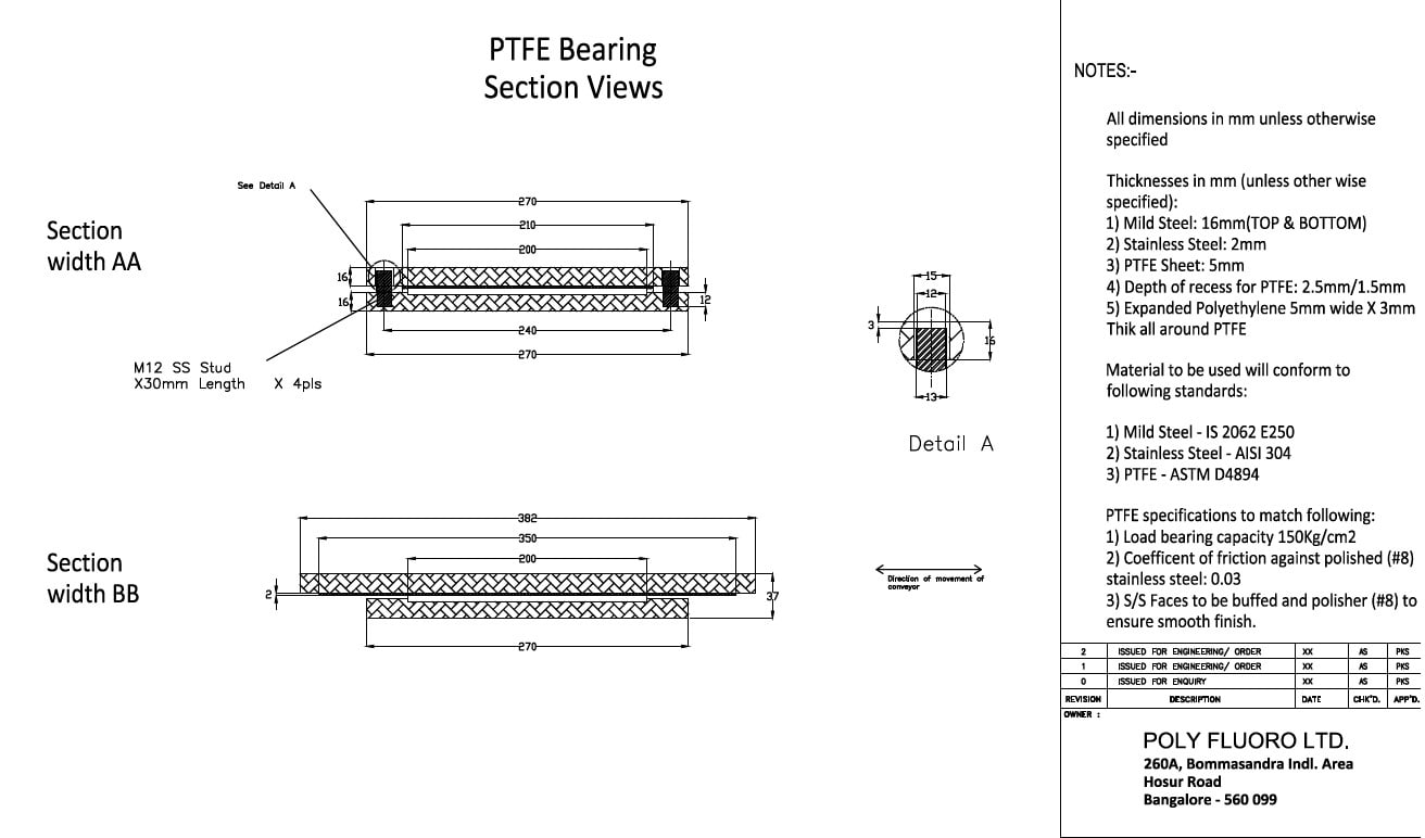
On the face of it, a PTFE sliding bearing - also called a sliding plate bearing, a bridge bearing, a bearing pad or a Teflon sliding plate - is a simple assembly. Primarily, it consists of only 2 layers – a PTFE plate and a polished stainless-steel plate. These two materials are known to have the lowest coefficient of friction between any two solids and slide over each other effortlessly, especially when subjected to high pressures. In order to keep the PTFE in place, a mild steel plate is normally used as a backer. Since PTFE does not bond easily to other materials, this mild steel plate is often recessed, with the PTFE being bonded within the recessed pocket. This ensures the PTFE plate stays in place, even under high shear loads. This mild steel-PTFE combination is called the lower element. Similarly, as polished stainless-steel is expensive and since only a layer of about 2mm is needed anyway, another mild steel plate is used as a backer for the stainless steel. In this case, the stainless steel is stitch welded to the mild steel to ensure that it stays in position over the long term. This mild steel-stainless-steel combination called the upper element.
Having thus defined the basic form of the bearing, the other aspects of design can now begin to take shape. Often, these parameters will be defined by the client, leaving it to the manufacturer to both design the sliding bearing accordingly and prove – using calculations based on material properties – that the specified parameters can indeed be accommodated. These include:
1. Vertical load – possibly the most relevant parameter. A PTFE sliding bearing needs to be able to comfortably hold the compressive load being placed on it. Since steel has a far higher compressive strength than PTFE, the design focusses on the area of PTFE to be used, considering PTFE’s own compressive strength. It should be noted that while PTFE is capable of taking loads as high as 400 Bar (40Mpa), designers would do well to take a safety factor of 50-60% against and consider a compressive strength of 150-200 Bar when making calculations. Once the quantity in square centimetres is established, the exact length and width can be altered to suit the size of the portal plate on which the bearing is to be installed.
2. Longitudinal movement – The whole purpose of a PTFE sliding bearing is to accommodate movement while taking vertical loads. In the case of certain structures – such as pipelines - the linear thermal expansion of the system can be so high that between morning and noon, the bearing may be required to slide over 100mm in either direction. Movement dictates the extent to which the stainless-steel sheet would be required to extend beyond the PTFE plate.
While on its own, movement seems like a simple matter of adding the value of the total expected movement to the size of the PTFE plate, movement also creates an issue of cantilever loads. The further the upper element extends beyond the lower, the more chances there are of bending. Thus, care also needs to be taken to ensure that the thickness of the mild-steel plate in the upper element is high enough that bending will be avoided
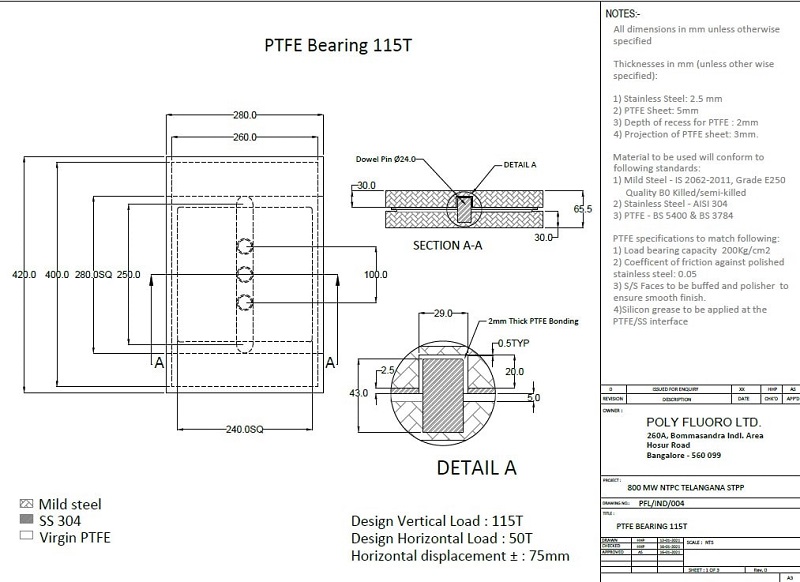
3. Lateral movement – while some sliding bearings are free to slide in all directions (aptly called: free sliding bearings), for the most part, a bearing only needs to slide longitudinally. This means that in the lateral direction, movement would be restricted. To ensure this, either guide plates can be used along the side of the bearings or dowel pins can be incorporated on to the lower element, which would sit inside longitudinal slots on the upper element to prevent lateral movement.
The key consideration here is the extent of lateral load expected. Based on the same, the dowel pin can be designed such that it will not bend.
4. Uplift loads – many structures may experience uplift loads due to either heavy winds or some mechanical characteristics of the system. This can cause a misalignment in the bearing or – in the worst case – even cause the upper element to slip off the lower element completely, causing major structural damage.
Such uplift loads can be accommodated by the use of brackets or a T-shaped dowel pin. Care needs to be taken that the load on the pin does not exceed the tensile strength of the pin itself. To ensure this, we usually employ pins using stainless steel, where the tensile properties allow for higher loads on the same size pin.
In addition to the strength of the dowel pin and/or side guides, it is important to note that a sliding bearing is all about reduced friction. It means little that the PTFE and stainless-steel would slide over one another if there is friction between the guiding elements themselves. Hence, special care needs to be taken to ensure that the gap between the pins and the slots in the bearing are sufficient to allow for free movement. In addition to this, PTFE would need to be used between the slot and the pin to ensure that even if the pin came into contact with the slots, sliding movement would still take place. This is another reason that stainless steel is used for the dowel pin, as it can be polished to ensure a minimal coefficient of friction.
5. Rotation – while most sliding bearings require very minimal rotation (fractions of a degree), there are some assemblies where the flatness of the system could be compromised, causing the upper and lower elements to lose some contact. Employing an elastomer – like neoprene or even silicone – allows the bearing to compensate for this to some extent. Given the nature of the elastomer, higher rotation can only be accommodated by increasing the thickness of the said elastomer, which in turn can cause issues with stability. In such a situation, a spherical bearing arrangement could also be designed in to increase the allowable rotation.

Our own experience with PTFE sliding bearings has shown us that oftentimes, the bearing is the last thing to be designed. In many cases, we have heard that the project has been in the last stages of completion and the bearing was either forgotten or it was otherwise assumed that it was an off-the-shelf item that could be supplied ex-stock! The result of this is that the bearing manufacturer needs to work around constrains such as the size of the portal plate and/or the available gap between the sub and superstructures within which the bearing needs to fit. Sometimes there are even restrictions on welding or bolting, meaning the bearing manufacturer has to design something that can be installed on site with minimal fitment.
The result of all this is that a PTFE sliding bearing is usually a premium product and that a good manufacturer needs to understand all the parameters such that an effective solution can be supplied, often with very little lead time. It is rare that we have even supplied the same bearing twice, because with each new project, the bearing needs to evolve to meet the project’s peculiarities!
Read More
1. Shear Load Considerations for PTFE Sliding Bearings
2. PTFE Sliding Bearings: Calculating Coefficient of Friction