Unravelling Polymers

The Definitive Blog on Polymers by Poly Fluoro Ltd.

Expanded PTFE (ePTFE) Tapes - Properties and Installation Techniques

ePTFE Tapes are an ideal form-in-place gasket material made from 100% pure virgin PTFE that has been expanded to achieve a foamy structure.

While we have covered the applications of this earlier and also touched upon some of the variants, we would like to re-explore some of the finer aspects of the material as well as look at the installation in more detail.

ePTFE Structure

A number of variables contribute to what we would define as a suitable final product. While the nuances of the production technique are proprietary information, what we can reveal is that the end product, while seemingly uniform, can be anything but.

  1. Specific Gravity In achieving a final product that matches the properties of other ePTFE Gasket Tapes in the market, one of the key properties explored was the density of the material. By varying the process, this parameter can be altered to produce different results. While most commercially available ePTFE Tapes have a specific gravity of 0.6-0.7, we were able to bring this down to 0.3, making the material much softer and more malleable.

    This reduction in density is not always preferred. In applications where the ePTFE is sandwiched between steel elements, you would prefer a higher specific gravity. However, in delicate applications, such as electronics and medicine, we may need to use a gasket or sealing element upon which large pressures cannot be applied as the equipment themselves are fragile. In such cases, a low density tape would be ideal as it would take the shape required with minimal pressure

  2. Thickness Standard ePTFE tapes come in thicknesses starting from 1.5mm. However, certain applications such as cable wrapping and filtration require tapes as low as 0.1mm in thickness. While achieving was not easy, it did allow us to explore the properties of tapes under 1mm in thickness and gauge what made them so different.

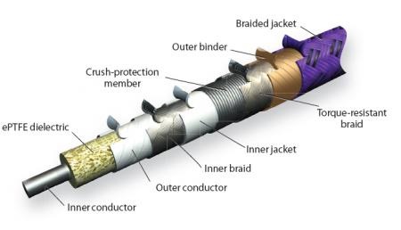
    ePTFE Tapes fall somewhere between sintered PTFE tapes (made from skiving a fully sintered PTFE billet) and thread sealant tape (made from calendaring unsintered PTFE strips). As such, they imbibe the electrical properties of skived tapes, while retaining the malleable structure of thread sealant tape. Furthermore, the foamy structure allows for better thermal insulation as compared to both the other variants

  3. Fillers Fillers are commonly used in PTFE to attain variations in final properties. We have experimented with fillers of PEEK and Carbon to reveal variations that significantly improve what the ePTFE tapes are capable of. Carbon allows us to make anti-static tapes, which are used extensively in the manufacture of co-axial cables. PEEK, meanwhile allows for vastly improved wear properties, while not violating any dielectric parameters or FDA parameters.

    In addition to this, we will be looking at fillers of glass and graphite. Each will bring its own unique alterations to the material.

Sizes available

FluoroFoam ePTFE gasket tape is an ideal solution for flange connections, container rims, and any other metal to metal application requiring a compressible, chemically resistant seal.

The tape comes with a one-side adhesive that aids in the installation by allowing exact placement of the gasket lining.

  Standard Spool Lengths (others on request)
Size (mm) 5m 10m 25m 50m
1.5 x 3    
2 x 5    
2.5 x 7    
3 x 10  
4 x 12  
5 x 14    
6 x 17  
7 x 20  
5 x 25  
5 x 28    

Installation guidelines:

Completely clean the sealing area and remove any dirt, corrosion, oil or leftover from old gasket material.

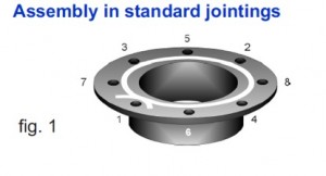
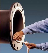
Cut one ending of the sealing tape and remove just a little of the protecting paper. Place the tape at the nearest possible position next to the bolts, starting next to a bolt hole. Fit the gasket around the entire flange circumference and across the endings as shown in figure 1.

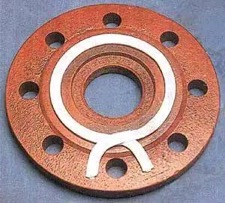
Assembled in fragile flanges apply techniques as shown in figure 2. Skive the endings as shown in fig. 3 and overlap according to the recommended overlap length. Cut off the excess, tapering to the end, leaving a total thickness of approx. 120 %.

At least 4 progressive torque sequences with a torque wrench, in a star of 180° (fig. 1), should follow the first torque by hand.

Lastly, perform a circular torque to check and ensure a tight and long-lasting seal.

ePTFE flangeFig 2

Fig 3

Photos of typical applications:

ePTFE Flange

The ePTFE Tape is allowed to overlap at the ends to ensure complete sealing.
Due to the softness of the tape, this overlap is accommodated during compression causing no variation in thickness

ePTFE Adhesive

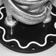
The one-side adhesive backing allows installation even on vertical surfaces, eliminating the need for grooves, clamps or bolting arrangements.

ePTFE metal to metal

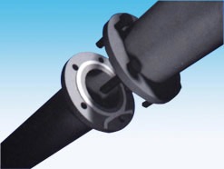
Metal-to-metal flange connections benefit greatly from the use of FluoroFoam ePTFE.
The ePTFE takes the exact shape of the gap between the two metal members ensuring a perfect seal with minimal effort

ePTFE heat exchanger

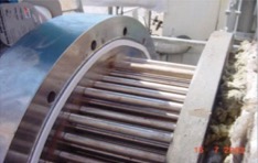
Form-in-place ePTFE gasket tape can effectively seal flanges on large shell-and-tube exchangers
Available in running lengths – the tape saves big on cost in areas where large, custom made gaskets would be too expensive

ePTFE form-in-place

The versatility and texture of the material ensure that there is no shape that cannot be attained.
This adds to the effectiveness as well and reduces costs significantly compared with custom made gasket and sealing solutions

Advantages of FluoroFoam ePTFE Gasket Tape:

  • Quick and simple installation: adhesive strip makes installation easier while the shape and versatility of the material means minimal cutting and sizing
  • Reduced downtime: standard sizes are immediately available ex-stock
  • Reduced stock: a few spools of different sizes cover most applications within a plant
  • No risk: the texture of FluoroFoam ensures the material accommodates the shape of the mating member, so there is no chance of the equipment getting damaged by the ePTFE
  • Safe: ePTFE is chemically inert and can, therefore, be used even in the harshest environments without risk of reacting with the surrounding substances
  • No waste: FluoroFoam comes in a spool, so no material gets wasted
  • Cost-effective – FluoroFoam can be used to replace custom made gaskets that are expensive and made-to-order. This is results in a huge cost saving in larger diameter pipes and vessels. 

Technical Details:

  • Temperature range: – 240°C up to +260°C, for short periods up to +310°C
  • Chemical resistance: resistant against all chemicals from pH 0-14 – except molten alkali metals and elemental fluorine at high temperature and pressure
  • Pressure resistance: vacuum up to 200 bar
  • Density: 0,65 g/cm³, +/- 0,1g/cm³ (for rectangular cross-sections only)
  • Aging resistance: FluoroFoam itself does not age and is UV-resistant. However, the adhesive backing may lose its effectiveness if kept unused for too long
  • Colour: white (other pigments available on demand)
  • Fillers: FluoroFoam can be offered in virgin and carbon filled variants
  • Others: FluoroFoam is physiologically harmless. It has no smell or taste. It is neither contaminating nor toxic. It is made using FDA approved raw materials

Solar Tracker Bearings - Finding the Right Polymer Solution

Many believe that solar energy is the ideal path to ensuring a green, sustainable future. However, few realize that commercially, their financial viability is constantly threatening those very pioneers who boldly invest their funds into making this vision a reality.

We were recently asked to review the requirements of a 55 Mega-watt solar power plant in South India. Driving into the plant, one had to admit that the absence of smoke and noise alone made the idea of solar power appealing in contrast to its traditional coal-based variant. Things within the plant were not quite as peaceful. Despite the rated power, the plant was only operating at about 40 MW. This was because the unpredictability of sunlight made the whole operation highly subjective – with engineers having to take a call on whether or not to start the plant based on the extent of cloud cover on the horizon. Starting the plant is a 45-minute process which also consumes a lot of power. Hence, turning the plant on was both an investment in time and money. Unless the resulting power generated justifies this expense, there was no point in turning the system on. Add to this that unlike a coal-powered plant – which can run non-stop – solar plants need to shut down at the end of the day. So each day, the financial decision to turn the plant on is visited anew.

Our own inputs were called upon for two reasons. First, the client was looking for a solution to prevent the shattering of the glass reflecting panels. Panels were arrayed along a stretch, but an irregular spacing between these panels meant that in some cases, the mirrors were too close to one another. In the event of strong winds, there was a high chance that they would collide and shatter. To remedy this, we were asked to look into the prospect of making a polymer fixture that would be sturdy enough to hold the frames of the mirror panels in place. When we inquired why a simple metal rod could not be used, we were informed that the power consumed in having the panels track the sun’s movement was significant – so a metal fixture would only increase the weight further, adding to this expense.

Another area of the requirement was in the solar tracker bearing. All solar panels have a tracking mechanism to follow the sun’s movement. The mechanism that moves the panels needs to have an effective bearing element that can minimize the static coefficient of friction and endure for an extended period of time. Most specifically, solar tracker bearings need to encompass the following:

  1. Self-lubrication – since the volumes of these bearings tend to be large, it may not always be possible to lubricate the mechanism regularly. In such a case, self-lubricating bearings are ideal.
  2. Lightweight – as mentioned above, solar plants rely on pockets of sunlight in which they can effectively generate energy. Hence, the aim to maximize the output when the plant is functional is critical to the financial viability of the system. One way to do this is to use materials that place as little load on the mechanisms as possible
  3. UV and weather-resistant – It goes without saying that any component used in a solar tracker system will be exposed to generous amounts of sunlight. In addition to this, the effects of rain and general weathering would also need to be accommodated. Plants are usually set up with a time horizon of at least 25-30 years. It is reasonable to assume that a good bearing solution will not need replacement during this time frame.
  4. Wear resistance – again, the constant movement of the system entails a wear resistance bearing that will not yield during the life of the plant.
  5. Cost-effective – finally, the volume of bearings required in a single plant can be up to 2000 pieces per Mega-watt. This means that cost is also a criterion that must be looked into when designing the same.

The right polymer solution needs to encompass all the above properties. There currently exist a number of bearing types manufactured by companies in Europe and the USA. Most of these, we are told, rely on a combination of PA6 (Nylon 6) with either glass or molybdenum-di-sulfide. The filler materials provide the wear properties while Nylon 6 is reasonably light-weight, has good self-lubricity and is reasonably priced. In order to make the polymer UV resistant, the material is pigmented black.

In India, the interest in polymer solar tracker bearings has recently spiked. While many OEMs are keen to replicate the materials used abroad, care must be taken to ensure that the properties are all met factoring our local conditions.

Firstly, the harsher weather and heat in India calls for a more robust polymer. In addition to this, the ad hoc nature of the system means that the polymer is subjected to sudden loads, which it must be able to absorb.

While we have been recommending PA6 to a number of clients, we understand that for India, UHMWPE may be a better option. The material exhibits superior wear properties and has a coefficient of friction comparable to that of PTFE. Compared with PA6UHMWPE is 20% lighter and is also capable of taking high loads. Finally, a price comparison would also show that UHMWPE is a more cost-effective solution.

It remains to be seen whether the adoption of UHMWPE in solar applications sees any growth. The industry is alive with activity an innovation, so perhaps it is only a matter of time.

ePTFE Applications in Cable Manufacturing

Despite extensive research into a new product, we are often introduced to applications that we had perhaps not considered and which open a whole new avenue of possibilities for the item in question.

Given the sheer versatility of ePTFE as a material for sealing, filtration, vibration dampening, and corrosion protection, it came as little surprise to us to learn that its electrical properties open up applications into the cabling industry.

ePTFE vs PTFE

ePTFE or Expanded PTFE is a variation of pure or solid PTFE. The material is processed in a way that infuses air into the solid PTFE to give it a spongy, malleable texture that makes it a preferred material for sealing applications. The same texture – being comprised of 70% air, also lends itself to vastly improving electrical conductivity and dielectric strength.

We already know the properties of pure PTFE in electrical applications make it an insulator of unparalleled effectiveness. The invention of ePTFE resulted in a material that was up to ten times lighter and nearly halved the dielectric constant from 2.1 to 1.3.

So while many high-performance cables use solid PTFE (by way of paste extruding PTFE tube on to a conductive core), wrapping the core in ePTFE offers added possibilities in cabling.

ePTFE Tapes in Cabling

ePTFE insulator tape can be made with tightly controlled thicknesses of as little as 0.05mm, with a uniform density, and dielectric constant. Wrapping individual conductors in ePTFE can cut interference, noise, cross-talk, and signal attenuation. In some applications, ePTFE tape helps limit phase shift to 4.3° and signal attenuation to 0.05 dB at 110 GHz.

High-dielectric ePTFE insulation can be up to 50% thinner than other materials.

At higher voltages, corona discharge also becomes a concern. We have modified PTFE for better performance in wires carrying 5 kV and higher voltages. Corona-resistant (CR) PTFE eliminates the microscopic voids between conductor and insulation that can be corona- discharge initiation sites, especially in high-altitude, military, and space applications.

Shielding is the furthest from the cable’s neutral axis, so it sees the greatest flexure stress. Cutting shield-to-conductor and shield-to-jacket friction deters heat generation and keeps stress off the shield.

Placing ePTFE binders on either side of the shield (with coefficients of friction as low as 0.02) lets each conductor slide past its neighbors and the outer shield with ease, making the cable as a whole more flexible in rotation and torque, and eliminating internal abrasion. Designers who know a cable will not lose strength over time through abrasion can tighten the design envelope and still extend cable life.

ePTFE Cable

Any cable jacket must protect the shields and conductors from the environment and lend extra tensile and flexural strength. Like conductor insulators, jacket layers should be thin, resist tears, withstand fluid attack, and have high tensile strength.

Many applications use durable polyurethane (PU) jackets. For environments that require low particulation, polyvinylchloride (PVC) may be a better choice.

Jackets can also be made of ePTFE for additional insulation and resistance to chemical attack. If the cable assembly slides through other machine parts, abrasion-resistant ePTFE is a good choice for extending cable life.

The advancements in ePTFE manufacture allow for uniformly thick tapes in running lengths of over 1000 meters. This opens up a world of possibilities for cable manufacture that is only now being harnessed around the world.