Unravelling Polymers

The Definitive Blog on Polymers by Poly Fluoro Ltd.

ePTFE Applications in Cable Manufacturing

Despite extensive research into a new product, we are often introduced to applications that we had perhaps not considered and which open a whole new avenue of possibilities for the item in question.

Given the sheer versatility of ePTFE as a material for sealing, filtration, vibration dampening, and corrosion protection, it came as little surprise to us to learn that its electrical properties open up applications into the cabling industry.

ePTFE vs PTFE

ePTFE or Expanded PTFE is a variation of pure or solid PTFE. The material is processed in a way that infuses air into the solid PTFE to give it a spongy, malleable texture that makes it a preferred material for sealing applications. The same texture – being comprised of 70% air, also lends itself to vastly improving electrical conductivity and dielectric strength.

We already know the properties of pure PTFE in electrical applications make it an insulator of unparalleled effectiveness. The invention of ePTFE resulted in a material that was up to ten times lighter and nearly halved the dielectric constant from 2.1 to 1.3.

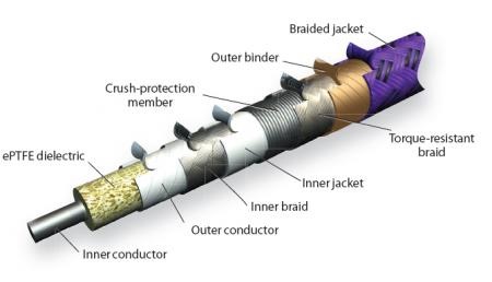
So while many high-performance cables use solid PTFE (by way of paste extruding PTFE tube on to a conductive core), wrapping the core in ePTFE offers added possibilities in cabling.

ePTFE Tapes in Cabling

ePTFE insulator tape can be made with tightly controlled thicknesses of as little as 0.05mm, with a uniform density, and dielectric constant. Wrapping individual conductors in ePTFE can cut interference, noise, cross-talk, and signal attenuation. In some applications, ePTFE tape helps limit phase shift to 4.3° and signal attenuation to 0.05 dB at 110 GHz.

High-dielectric ePTFE insulation can be up to 50% thinner than other materials.

At higher voltages, corona discharge also becomes a concern. We have modified PTFE for better performance in wires carrying 5 kV and higher voltages. Corona-resistant (CR) PTFE eliminates the microscopic voids between conductor and insulation that can be corona- discharge initiation sites, especially in high-altitude, military, and space applications.

Shielding is the furthest from the cable’s neutral axis, so it sees the greatest flexure stress. Cutting shield-to-conductor and shield-to-jacket friction deters heat generation and keeps stress off the shield.

Placing ePTFE binders on either side of the shield (with coefficients of friction as low as 0.02) lets each conductor slide past its neighbors and the outer shield with ease, making the cable as a whole more flexible in rotation and torque, and eliminating internal abrasion. Designers who know a cable will not lose strength over time through abrasion can tighten the design envelope and still extend cable life.

ePTFE Cable

Any cable jacket must protect the shields and conductors from the environment and lend extra tensile and flexural strength. Like conductor insulators, jacket layers should be thin, resist tears, withstand fluid attack, and have high tensile strength.

Many applications use durable polyurethane (PU) jackets. For environments that require low particulation, polyvinylchloride (PVC) may be a better choice.

Jackets can also be made of ePTFE for additional insulation and resistance to chemical attack. If the cable assembly slides through other machine parts, abrasion-resistant ePTFE is a good choice for extending cable life.

The advancements in ePTFE manufacture allow for uniformly thick tapes in running lengths of over 1000 meters. This opens up a world of possibilities for cable manufacture that is only now being harnessed around the world.

Lubring - Special Notes on Bonding and Finishing

As a globally reputed manufacturer of Lubring Slideways, we are frequently asked to provide technical assistance with regards to the bonding and finishing of the material.

Lubring is a slideway bearing material that is used primarily in machine tool building and reconditioning. As such, the machine builder is usually equipped with enough know-how on the bonding and subsequent planing of the material, such that it forms the most effective bearing surface. However, we often supply to dealers or first time builders, who need more assistance on the bonding process.


Preparation:

The metal surface to be mounted with Lubring Slideway can be prepared by the normal machining methods such as grinding, milling, shaping, and planning. The surface roughness of all forms of preparation should be preferably between Ra = 1.6 µm and Ra = 3µm and not more than Ra = 6µm.

Once roughened the surfaces can be cleaned with Trichloroethylene, Perchloroethylene or Acetone. Slideway bearing material should be cleaned similarly.

Bonding:

For bonding of Lubring Slideway the following resin adhesive can be used: Ciba Geigy’s Araldite – Hardener – HV 953U; Araldite AW106. The Araldite should be applied both to metal and slideway and be spread as uniformly as possible by means of a serrated spatula. To obtain the best dispersion of the adhesive, when spreading on the slideway brush in the longitudinal direction; when spreading on the metal, brush in the transverse direction. The total quantity of bonding should be approximately 200gm per sq. mt.

Hardening:

After mounting the slideway a clamping pressure of between 0.1 – 0.3 kp/sq.cm is recommended. It is important to keep the pressure constant during the hardening process. Due to the differences in the thermal expansion coefficient of the materials, the maximum curing temperature should not exceed 40°C. The hardening time for various temperatures is 20°C min 15 hours; 25°C min 12 hours; 40°C min 5 hours.

Finishing:

After curing of the adhesive, the Lubring Slideway can be machined by conventional means. The choice depends on the machinery available viz.: grinding; grindstone.

Grinding: For grinding of Lubring Slideway use the same speed as grinding cast iron, taking care that sufficient cooling is used with an ‘open ’stone. The grindstone should be preferably silicon carbide based with rubber or polyurethane binding; grain size 80-30. Alternatively, aluminum oxide with rubber bonding may also be used for soft, fine grinding action, pre-polishing, and pre-mating treatment.

Oil Grooves: Lubring Slideway can be machined with oil grooves using the same methods and cutting data as used for cast iron. The form and depth of the oil grooves are optional. However, the oil grooves should never pierce through the Lubring Slideway. Oil grooves should be away from the edges by 6mm.

Metal Mating Surface: The metallic mating surface running against the Lubring Slideway should be finished to 16 Ra for optimum performance. The surface finish must never be below 14 Ra or above 20 Ra as applicable to cast iron or steel. This surface finish should be obtained by grinding in the direction of travel. Do not lap or polish to obtain this surface finish.


The above parameters provide an effective guideline not just for Lubring, but for bonding all PTFE-related items to metal.

Do visit our website for more details

A Comparison of Dimensional Stability Among High-Temperature Polymers

In the world of engineering polymers, plastics capable of withstanding temperatures above 150°C come at a price. While Polyamides, POM (Delrin®), and PVDF (Kynar®) are all well suited to temperatures within this barrier, when we look beyond we find the options become rather expensive.

Polymers that can accommodate higher temperatures, such as PTFEPEEK, and Polyimides tend to be in the range of 3x-20x the price of lesser plastics. As a result, the cost implications of designing a system using high-temperature polymers are significant.

What do we mean by high-temperature polymer?

While the phrase seems fairly self-explanatory, high-temperature polymers need to be further evaluated to understand exactly how they behave. Usually, an OEM or product designer will look for the continuous service temperature to assure themselves that a part made using the polymer can withstand the conditions it will be subjected to.

Polymer Common Brand Name Glass Transition Temperature (°C) Continuous Service Temperature (°C) Melting Point (°C)
PTFE Teflon® -20 260 375
PEEK Victrex®/Ketaspire® 150 250 340
Polyimide (PI) Kapton® 400 450 NA
Polyetherimide (PEI) Ultem® 220 185 250
Polysulfone (PSU) Udel® 190 170 350
Polyphenylsulfone (PPSU) Radel® 220 180 370

However, for the component manufacturer, the service temperature is less relevant than the melting point and the glass transition temperature of the material. This is because these are the temperatures that directly impact the production of the component – both in molding as well as machining. We will be focusing here on glass transition temperatures and trying to understand how this metric needs to be used in component design and manufacture.

What is glass transition?

Put simply, a material moves from crystalline to amorphous states beyond its glass transition temperature. All polymers, when in a crystalline state, have internal stresses that keep it dimensionally stable. These stresses are a culmination of the inherent molecular arrangement of the molded shape and further stresses lent to it during the machining stage. Heating the part above the glass transition point causes the molecules to realign, thereby relieving the stresses and causing dimensional changes to the part. As stress due to machining can be significant, most polymers are subjected to an annealing cycle prior to machining, to ensure that the stress build-up does not cause the part to crack during the process. Polymers such as PEEK will crack under so little as a simple turning operation of not annealed beforehand.

The stresses are very relevant for machined components, as it ensures that machined parts subjected to temperatures within their glass transition point will not deviate dimensionally. However, it is equally true that in the event of higher temperatures, the deviation may result in part failure. This is typically the case for highly machined components.

Consideration for Dimensional Stability

Our experience with dimensional stability rests around the use of PTFE and PEEK. Both polymers behave very differently both during machining and after. We shall look at them one by one.

PTFE

Among high-temperature polymers, PTFE is unique in that it has a glass transition temperature under 0°C. The implication of this is that PTFE is generally amorphous even at room temperature and therefore does not suffer the internal stresses that other polymers do. As a result, PTFE typically does not require annealing, although it is still done as a means to improve the hardness of the material. No internal stresses mean that the material undergoes minimal duress during machining and any cracking of the machined part is avoided.

The flip side of this property is that PTFE has very weak dimensional stability when subject to applications where a high range in temperatures may be present. While PTFE can easily withstand high temperatures, close tolerances would need to be abandoned when subjecting it to these conditions as the material itself experiences an up to 3% deviation in linear dimensions between 0 and 100°C.

So although PTFE is capable of surviving the harshest of environments, a PTFE part machined with close tolerances is usually employed only in areas where the temperature, while high, must remain range-bound within +/-15°C.

PEEK

In contrast to PTFE, achieving close dimensional tolerances in PEEK and difficult due to the constant build-up of stress during machining. In our own experience, PEEK parts may sometimes need to be annealed multiple times to ensure that after each stage of machining, the internal stresses are adequately relieved so that the part does not crack/deform after the next stage.

Unlike PTFE, which constantly gives off heat as it is applied to it, PEEK needs external help in cooling it down. As a result, the use of coolant is common in PEEK machining and helps reduce the extent of stress-induced in the part.

Finally, while close tolerances of up to +/-0.01mm have been achieved on PEEK parts, there is no guarantee these tolerances will be retained should the part be subjected to a temperature above its glass transition point during application. In such an event, stresses induced during the final operation of machining will relieve themselves and cause the molecules within the PEEK material to realign slightly, causing dimensional deviations in the part.

So given the above hazards, why are PTFE and PEEK still so widely used? One reason is that there exist very few applications where strict dimensional stability in temperatures above 200°C are a co-requisite. Hence, we have applications of high temperature where the dimensional tolerances tend to be very lax and we have applications with tight machining tolerances, where the part may experience a maximum temperature of only 150-160°C.