Unravelling Polymers

The Definitive Blog on Polymers by Poly Fluoro Ltd.

Applications and Considerations for PTFE Seals

As a sealing element, PTFE has proven itself many times over. PTFE is used in seals because it encompasses all the properties essential for a good sealing element, mainly:

  • High wear resistance
  • Low coefficient of friction
  • Moderate hardness (allowing for better overall mating with metal parts)
  • Durability – both with temperature as well as corrosion

While these properties are not new to us, every material has a limit to how much it can withstand. Furthermore, every grade of PTFE offers something different to the sealing application. Understanding these limits and differences gives us a better understanding into choosing and applying PTFE seals to best suit the requirement.

Sealing is vital to almost any mechanical assembly. It serves to both retain fluid within the assembly and allows the assembly to function freely. A good sealing material – such as PTFE, needs to be elastic enough to close gaps and assist with the fluid retention while strong enough to take the wear load applied on it by (usually) metal mating parts. Still, within any assembly, there is likely to be some trade off between fluid retention and durability, and this is where the choice of grade becomes important. Typically, the following metrics needs to be studied:

Surface Finish

PTFE wears off in layers, and will usually deposit a coating on the mating surface. In general, it is easy to attain a surface finish of as high as Ra < 0.4 on a virgin PTFE part. However, once we introduce other materials such as glass, carbon, graphite or bronze into the mix, there is a huge drop in the finish. We have successfully attained a finish of Ra < 1.2 on PTFE+15% Glass seals – but going below this is always a challenge.

For the mating part, the surface finish is somewhat more important – as it is usually a metal and can wear the PTFE out significantly faster if not properly finished. When the metal surface is rough, more wear occurs until the crevices and valleys within the metal are filled with PTFE. PTFE will wear in direct proportion to the surface finish. Testing shows that the life of the seal is doubled when the finish is improved from 16rms to 8rms.

Surface finish also affects the sealing ability of PTFE. A rough finish creates microscopic “line of sight” channels allowing a flow path through mating parts. Hence, when sealing gases with small molecules, such as, hydrogen, helium, or oxygen, a 2-4 rms is highly recommended.

Hardness

When the mating part is hardened (via heat treatment or plating), there is a significant improvement in the life of the seal. Typically, when a hard and soft surface are in contact, there is an exchange of ions, which can lead to adhesion. This reduces the effectiveness of the seal. Improving the surface hardness of the metal part can control the adhesion.

PV Value

PV is an often-quoted metric for all PTFE grades. It offers a trade-off between the pressure that the PTFE can take, against the speed at which the mating part is sliding against the PTFE.  Understanding PV is key to understating whether the PTFE grade being considered at would be able to withstand the combination of load and RPM involved.

Disregarding PV values would almost certainly lead to a failure in the seal to perform. We have received many requests to look into the replacement of standard phosphor-bronze bushings, bearings and seals with PTFE grades. In most cases, PTFE looks to be a perfect substitute along most metrics. However, when we look at the pressure it can withstand under high RPMs, PTFE is not always suitable.
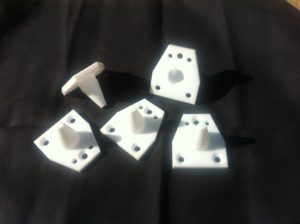
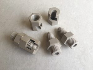
Types of seals

Given the diversity in automotive and mechanical applications, a number of different PTFE seal dimensions have been developed – each with it’s own unique property. When we cross these dimensions with the different PTFE grades, we end up with potentially hundreds of sealing options. Thus, choosing the right seal is important and a lot of thought needs to go into the same, before a decision is made.

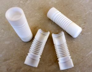
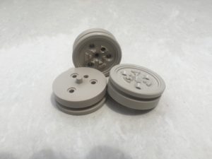
The spring-energised seal is a sealing device consisting of a PTFE ‘energized’ by a corrosion resistant metal spring.  Put simply – as PTFE is a soft material, it can be easily deformed by the metal parts surrounding it. The spring acts as a strengthening medium – allowing the PTFE to take loads while also applying force on the sealing surfaces to create a tighter fit and ensure no leakages. The spring also provides resiliency to compensate for seal wear, gland misalignment or eccentricity.

Types of such spring energized seals include:

Finger Spring:

This is mainly used in dynamic applications, has good sealing and a low coefficient of friction. It is recommended for surface speeds up to 250ft/min.

Coil Spring:

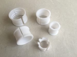
This is designed for more static or slow dynamic applications. It is not as flexible as the finger design – owing to the fact that the spring is coiled and more rigid as a result. However, it is significantly better than the finger design in sealing – due to the uniform pressure applied on all sides by the coil spring.

Double Coil Spring:

A more augmented version of the single coil – this is designed for purely static applications, such as cryogenics. The increased load applied by the double coil significantly improves sealing ability.

O-ring Energised:

This can be used in both static and dynamic applications and offers a good balance between the seal-ability of the coil energised seal and the flexibility of the finger spring. It is typically incorporated in areas where metallic springs cannot be used due to compatibility issues.

Rotary Lip Seals

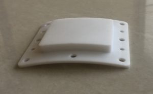
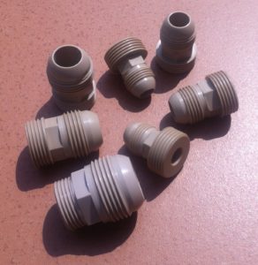
Lip seals are used primarily to seal rotary elements such as shafts and bores. They provide a self-lubricating medium between (usually) two metal elements – allowing for both smooth rotation and good sealing. Common examples include strut seals, hydraulic pump seals, axle seals, power steering seals, and valve stem seals.

Lip seals may be designed with or without springs – depending on the application.

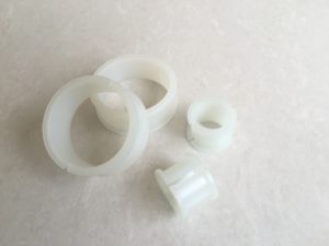
The examples shown above are merely indicative of the basic designs available in PTFE seals. In truth, each of the above types of seals may be expanded into many variants, depending on the exact requirements of the mating elements involved in the OEM designs. Furthermore, each may be provided in any of a number of grades of PTFE compounds available.

Choosing a PTFE compound for your PTFE seals

The grade of PTFE is a critical choice in the design of the seal. We have touched elsewhere on the variants and properties offered by the commonly used fillers in PTFE. In a nutshell – glass offers stiffness and creep resistance; bronze and molybdenum di sulphide offer wear resistance, but increase the coefficient of friction; carbon and graphite offer wear resistance and dimensional stability.

In our experience, a mixture of glass and molybdenum di sulphide offers the ideal sealing properties for most applications. However – the exact grade is usually a choice made by the OEM, based on what information we are able to provide.

The Many Chemical Applications of PTFE

PTFE is known to be among the most chemically resistant materials known to man. While this property is well known and often quoted in manuals and our own blog articles, we would like to touch upon some of the common applications that this property leads to.

PTFE Labwares

PTFE has been a mainstay in lab-ware items for a number of years. Lab-ware items include stopcocks, beakers, pipes, test tubes, stirrers, petri dishes and stands. In most labs, glass is the commonly used material for these items, but as we know, glass has a tendency to break. Furthermore, when dealing with harsh chemicals at elevated temperatures and pressures, PTFE becomes a viable option for a number of reasons.

  1. PTFE is chemically inert – barring certain alkalis at elevated temperatures
  2. PTFE does not break easily: Under loads, virgin PTFE would tend to deform rather than break. This makes it useful in applications involving high centrifugal forces – where a glass test tube might break under extreme loads
  3. PTFE is stable across temperature fluctuations: Even toughened glass would have a limit on how suddenly it can be cooled down when under high temperatures. PTFE is able to cool down rapidly from elevated temperatures without cracking
  4. PTFE is a great sealing material: Especially for stopcocks, PTFE forms a much better seal than glass equipment owing to the fact that it is soft and will easily seal gaps which may arise due to minor variations in taper between the pipe and the stopcock.
  5. PTFE is flexible: PTFE tube can be used in place of glass and be bent to accommodate the layout of the apparatus
  6. PTFE can be moulded with a magnetic core: PTFE stirrers are used because they can be moulded with a magnet at the core and used in magnetic mixers

PTFE Stirrers and Shafts

Stirrers and shafts are used primarily in highly corrosive applications including biotech, pharma and refineries. The ability of the PTFE to be constantly immersed in a chemical and neither modify nor be modified by the chemical makes it an invaluable component in many mixing arrangement.

More often than not, the shaft or stirrer needs to be custom moulded and machined to suit the mixing assembly. This makes it an expensive component and therefore only sparingly used. In some cases, a stainless steel core can be used over which the PTFE is moulded/ lined. In other cases, the stainless steel shaft can simply be coated with PTFE. However, this latter case only works where there is little or no abrasion expected on the shaft – since PTFE coating will peel off if the shaft is subjected to wear.

PTFE umbilical cords

Although the name sounds strange – the umbilical cord is a well-known arrangement of PTFE tubes used in the refinery industry. The purpose is simple – the refinery process yields a number of different gasses, which need to be analysed in a lab to gauge whether the right chemical reactions are taking place in the chamber. Taking these gasses to the lab (which needs to be a minimum of 200-250 meters from the reaction chamber) is a difficult process, as the gasses are corrosive and highly reactive – which may mean that they change composition during transit if not kept in a chemically inert environment.

An assembly of 12-15 tubes is bunched together using a PVC coating and each tube has a length of 250 meters and transports a single gas to the lab, where it is collected and analysed.

The complication in this design is that the PTFE tube needs to be continuous for the entire length of 250 meters. Any bonding or jointing leads to a foreign chemical in the tube and this affects the gas passing through it. After extensive trials, we find that using a welded joint comprised of PTFE is able to create an effective solution for the tubes.

Filtration

Many chemical applications involve multiple substances, which often need to be separated from one another. In such cases, PTFE becomes the preferred medium for filtration.

PTFE is used in 2 forms here:

  1. Porous PTFE sheet: This is a standard PTFE sheet skived from a porous PTFE billet. The billet is made porous by adding certain substances in the PTFE compound, which sublimate during the sinter cycle, leaving voids. These voids form the pores which aid in filtration. This type of membrane is not used extensively due to the inexact nature of the pores. However, the membrane can be made as thick as 5mm – which makes it useful in corrosive applications where a liquid needs to be separated from large solid particles.
  2. Expanded PTFE membrane: This is also called breathable PTFE membrane owing to the fact that you can pass gas through it, but not liquids. Expanded PTFE is more commonly used that porous PTFE as the pore size can be easily defined to within a few microns. It finds multiple applications in automotives, pharma and biotech.

PTFE Valves and Ball Valve Seats

Although valves and ball valves form an industry unto themselves and use a variety of materials other than PTFE, certain applications involving the flow of chemicals need PTFE valves to withstand the corrosion otherwise caused to non-PTFE valves.

Our own experience with PTFE valves sees it being used in piping systems in chemical plants and in equipments such as paint dispersion machines.

In paint dispersion, the equipment is used by retailers to mix different colours of paint to form a batch of a new colour as chosen by the customer. The paint passing through the PTFE valve needs to remain un-changed. Any reaction due to, say, using a nylon or PVC valve can alter the colour to the extent that the colour being chosen by the customer does not match the actual colour of the final paint. Thus PTFE is an invaluable component within this assembly.

Reprocessed PTFE and chemical applications

We had earlier done an article on reprocessed PTFE and the various issues it presents with regards to the base properties of the material. One of the issues we have observed is that when using reprocessed PTFE, the scrap is seen to change colour when using a coolant during machining. This came as a huge shock to us – as common opinion suggests that it is only in mechanical properties that the material suffers when reprocessed.

The finding leads us to believe that a number of things may be happening to cause this:

  1. There may be foreign substances used in making the reprocessed PTFE. Titanium Di-Oxide for example is a known additive in making PTFE appear whiter. Similarly – cheaper, un-tested additives may be added to improve appearance, which may not have the chemical inertness that PTFE has.
  2. Micro-impurities may be present in the material that cannot be seen by the naked eye. These may be reacting with the coolant causing the colour change
  3. The basic chemical structure may be altered on a microscopic level. PTFE is chemically inert because of its molecular structure, which involves a carbon atom, shielded by 2 atoms of fluorine. When we chemically etch PTFE, we effectively remove 1 flourine atom and expose the carbon atom, making it bondable. A similar transformation may be happening in parts of the material due to reprocessing – which cause a degradation in the chemical resistance of the material.

Precision Machining Polymers - The Challenges Are Plenty

Over the past decade we have seen a rapid shift from conventional machining to CNC machining. While CNC machined parts used to be required only in the most critical of applications earlier, they are now the mainstay, with even simple items like washers being churned out in this fashion, rather than depending on the perceived unpredictability of a manual system.

In the polymer space, while the shift to CNC has also been essential, there have been several complications that have arisen. We look at these here, in a bid to better understand the nuances of precision polymer machining and show that it is not always as straightforward as machining metals.

  1. Grades and varieties

    The first thing to realize is that the term “polymer” is both broad and vague. As a company deep rooted in PTFE (Teflon) as our core product, our experience into other polymers taught us that the differences in each make the process of CNC machining that much more unique. Let’s take a look at how some of the high-performance plastics behave:

    1. PA 6/ PA 66 (Nylon or Polyamide) – Nylon machines easily, but due to its low melting point, the feed rate and RPM need to be optimized to ensure that burrs do not melt and stick to the part. Furthermore, the high moisture absorption of Nylon implies that coolants can rarely be used, as these would ‘swell’ the component, causing dimensional deviations
    2. UHMWPE – like nylons, UHMWPE also suffers from having a very low melting point. Furthermore, as UHMWPE needs to be compression moulded, the orientation of the molecules within the part are not always predictable. Achieving high tolerances on UHMWPE is not always possible as a result
    3. PEEKPEI (Ultem)PI (Kapton) – these polymers are able to withstand high-temperatures and can therefore be run at higher speeds. However, due to the crystalline nature of the internal structures, the more stress applied during machining, the higher chance that the parts will crack. PEEK especially requires a special annealing process before it can be machined. In the event that multiple operations are required on a PEEK part, the part may be re-annealed between operations to ensure that the stress build up does not cause the part to crack later on.

      PTFE Radomes for Radar Applications

      Bellows – Virgin PTFE

      PTFE Radomes for High Precison Radar Applications

      PTFE Bobbins – Virgin PTFE – Tolerance of 0.04mm

      PEEK Adaptors for Aerospace

      PEEK Piston – Tolerance of 0.025mm

      PEEK Back Up Rings – 15% Carbon Filled

      PEEK Adaptors for Aerospace

      Nylon 66 Bobbins for Aerospace

      The above examples are just a few of the peculiarities that each polymer brings. With polymers such as PTFE (Teflon)DelrinPVDF (Kynar) and PVC, we have found the machining to be more straightforward. However, as the complexity of the part increases and the tolerances become tighter, the level of care needed increases, along with an increased need to understand the internal structure of the material.

  1. Tolerances and dimensions

    We are often approached by other companies also involved in some form of polymer machining, requesting whether we have any excess demand that they can support us with. Our first question is always “what tolerances are you able to achieve”?”. The answer is usually between 0.05mm and 0.1mm.

    From our perspective this is not adequate. While it is true that polymers do not lend themselves to the dimensional stability of metals (where tolerances of up to 1 micron are sometimes demanded), we have found that with the proper programming and handling, polymers can be machined to achieve a consistent tolerance of within 10-20 microns.

    It is in this endeavour that we have put a lot of our focus and effort. It is also why having CNC machines is alone not enough to ensure the parts would be of the highest possible precision. Knowing the material and understanding how the part needs to be handled – both during and after the machining process is complete, is critical to be able to get that extra 30-40 microns in tolerance.

    The other complexity on dimensions relates to the strength of the material. The longer the component, the tougher it becomes to attain close tolerances at the end – as the material starts to bend slightly, throwing the dimensions off. Again, knowing what the polymer is capable of and machining in a way that minimizes the deflection that the material would experience is key to ensuring a consistently machined component.

  2. Volumes

    While polymer machined parts have certainly found their foothold across industries, the volumes remain tiny when compared with metals, or even some injection molded polymer components.

    One of our concerns when shifting to CNC machining, was whether we could justify the expense against the low volumes of parts required. Keep in mind that apart from the machine cost itself, there are the added expenses of labour and special tooling.

    Getting high-volume parts that also demand the criticality that we offer remains a crucial challenge.

    Overall, the intricacies of polymer machining make it a rewarding experience. To be able to attain industry leading levels of tolerance across a whole range of polymers is something we are very proud of. So while CNC machining technologies certainly helped us move ahead, what set us apart was the ability to take the precision machining of polymers up a notch.