Unravelling Polymers

The Definitive Blog on Polymers by Poly Fluoro Ltd.

UHMWPE - the unknown polymer

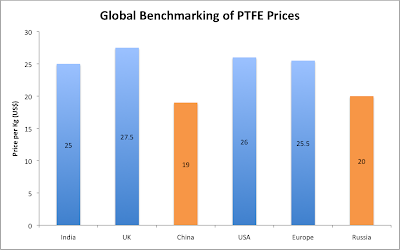
One of the few good things to happen due to the unprecedented escalation of PTFE prices globally was that it allowed us to look at alternate materials and seriously gauge the feasibility of manufacturing them.

In an earlier post, we looked at the various properties of PTFE and compared them to the other polymers. And although the key takeaway from that exercise was that PTFE was an immensely versatile material which was difficult to replace, we did make mention of possible alternatives, provided the user was willing to compromise on some parameters.

A key polymer which struck us then and continues to feature prominently in our product offering today is UHMWPE. We would like to take a more detailed look at UHMWPE for two reasons:

  1. It does measure up against PTFE as a low-cost substitute (with certain limitations)
  2. It’s properties do not seem to be as widely known to end-users, resulting in a limited use in many applications where it would otherwise be ideal

 What is UHMWPE?

Sometimes referred to as just “UHMW”, UHMWPE or Ultra High Molecular Weight Poly Ethylene is an off-white polymer that exhibits superior strength while being both light-weight and possessing a low coefficient of friction.

While it is not entirely accurate to refer to it as an “unknown” polymer – our own analysis of search terms within Google tells us that a total of ~62,000 searches per month are done globally for UHMWPE and/or UHMW. This is tiny in comparison to searches for PTFE/Teflon (1,300,000 per month) or for Nylon (5,500,000 per month).

Comparison with PTFE

So how does UHMWPE compare with PTFE? In our own opinion – it compares rather well. In fact, if you take all the applications involving PTFE and remove the ones that call for heat resistance, UHMWPE is a very workable substitute.

Although a full comparison chart is given at the end of this article, we would like to look at some specific properties more subjectively.

  1. Temperature resistance: Let’s get this one out of the way, since we know that it is UHMWPE’s weakness. Having an operating temperature of only about 80°C compared with 260°C for PTFE, UHMWPE is automatically disqualified in a range of industrial applications where the temperatures surrounding the material are expected to be well in excess of it’s upper limit.
  2. Wear resistance: Before we were familiar with UHMWPE, we were asked to advice a cement plant on whether they could use Lubring sheets (PTFE+Bronze) in a wear application. We were confident that it would work and when they mentioned that they had tried UHMWPE and it had failed, we did not think it was worth looking into. But when we did compare the materials, we realized that if UHMWPE had failed, there was little chance PTFE would work – since the gap between the two materials on this parameter is quite wide.Keep in mind that PTFE+Bronze is the most wear resistance grade of PTFE available. So if we compare UHMWPE with plain PTFE, the rift is even wider.
  3. Coefficient of friction: It is difficult to beat PTFE on this parameter, although UHMWPE comes fairly close. While it remains true that the coefficient of friction between PTFE and polished stainless steel is the lowest between two known solids (0.03-0.05), UHMWPE is able to reach a somewhat respectable 0.1-0.15 on this metric. While this does put it out of range for many applications where the recommended coefficient cannot exceed 0.1 (eg: sliding bearings) – it is a useful substitute in components where smooth movement between parts is the only requirement.
  4. Dielectric strength: Both materials are pretty much neck and neck on dielectric strength. Where UHMWPE loses out is on its ability to be skived into thin tapes. While we regularly skive PTFE down to 0.04-0.05mm thicknesses, the same is more challenging with UHMWPE, since it lends a much higher wear on to the skiving blade, making it difficult to achieve long lengths of tape before the blade dulls out and breaks the tape. Nonetheless, thicknesses of 0.1mm and above are more than feasible, meaning that as an insulating pad or even a component used in high voltage applications, UHMWPE is more than suitable.
  5. Chemical inertness: PTFE is well known for it’s inertness and this allows it to lend itself to applications ranging from biotechnology to medical devices and chemical linings. While UHMWPE does not have quite the same extreme inertness as PTFE, it does find use in medical applications (it is used in parts for joint replacements) and can easily be used in both biotech and chemical applications, provided the exact nature of chemicals is known and compared against it’s capabilities.
  6. Weight: While weight has never been a consideration for PTFE in any of it’s applications, we would still like to highlight that UHMWPE is less than half the weight of PTFE (specific gravity of 0.95 vs. 2.15 for PTFE). The key difference this adds is in their respective cost cacluations. Not only is UHMWPE cheaper in resin form (roughly 1/4th the cost per Kg), but the fact that you consume only half the weight to get the same volume of finished product implies that the effective cost is 1/8th the cost of PTFE. This represents a significant saving.

So where can we use UHMWPE?

There are a range of applications where UHMWPE could and should be used. In many cases, we have tried to suggest to the end-user that we can offer them UHMWPE in stead of PTFE, but due to restrictions on standards and because changing specifications can be time consuming, very few have opted for the change.

Strangely, in many cases, clients have opted for suppliers offering reprocessed PTFE, but not UHMWPE. Given the highly diminished properties of reprocessed PTFE, this is functionally not a great trade-off in the medium to long term.

  1. Automotives: Most automotive applications use PTFE in high temperature environments, so UHMWPE does not fit the requirement. However, there are a number of applications where the parts operate at room temperature eg: car doors, seats, hand levers etc. and here UHMWPE can find a lot of use. We are aware that the wear strip used inside car doors employs UHMWPE. In general, UHMWPE wear strips offer a low cost and effective alternative to PTFE wear strips.
  2. Valves and seals: Typically, valves and seals require a low coefficient of friction with a good wear resistance.  UHMWPE is an excellent replacement for PTFE in these areas.
  3. Medical: UHMWPE is widely used in joint replacements due to its chemical inertness and light-weight.
  4. Infrastructure: Although regulatory restrictions prevent materials other than PTFE to be used POT bearings, there are many sliding bearing applications which do not fall under the government codes and are therefore potential areas where UHMWPE can be used. UHMWPE could be employed successfully in sliding bearings and as plain sliding pads.
  5. Electronics: Many components used in electronics have traditionally employed PTFE components for insulation. In a number of cases, we have successfully tested UHMWPE for these applications and convinced the client to shift.

Overall, there continues to be a resistance to employ a material like UHMWPE. Part of this is regulatory – drawings and specifications that call for PTFE cannot be changed over night. But mostly there is a genuine dearth of awareness about the material – which is equally difficult to change. While it is true that UHMWPE is a substitute for PTFE – we see it as more of a partner in application – allowing many end-users to find a competitive, low-cost solution where they would otherwise be unable to proceed with their development or manufacturing.

Comparison chart between PTFE and UHMWPE

  UHMWPE PTFE Units
Colour Off-white White  
Specific Gravity, 73°F 0.944 2.25  
Tensile Strength @ Yield, 73°F 3250 4000 psi
Tensile Modulus of Elasticity, 73°F 155,900 150,000 psi
Tensile Elongation (at break), 73°F 330 350 %
Flexural Modulus of Elasticity 107,900 145,000 psi
Compressive Strength at 2% deformation 400 1650 psi
Compressive Strength 10% Deformation 1200 2200 psi
Deformation Under Load 6-8% 2.5-5% %
Compressive Modulus of Elasticity, 73°F 69,650 79,750 psi
Hardness, Durometer (Shore “D” scale) 69 55-65  
Izod Impact, Notched @ 73°F 30 161 ft.lbs./in. of notch
Coefficient of Friction (Dry vs Steel) Static 0.17 .06-0.12  
Coefficient of Friction (Dry vs Steel) Dynamic 0.14 0.12  
Sand Wheel Wear/Abrasion Test 95 90 UHMW=100
Coefficient of Linear Thermal Expansion 11 6-7.2 in/in/°F x 10-5
Melting Point (Crystalline Peak) 135-145 380 °C
Maximum Service Temperature 80 260 °C
Volume Resistivity >1015 NA ohm-cm
Surface Resistivity >1015 NA ohm-cm
Water Absorption, Immersion 24 Hours Nil Nil %
Water Absorption, Immersion Saturation Nil Nil %
Machine-ability Rating 5 3 1 = easy, 10 = difficult

PTFE Pricing Again - is there another price hike in the offing?

The adage “Only the paranoid survive” has held very true in the PTFE industry these past 20 odd months. You see, while it is difficult to imagine worst case scenarios and constantly plan along their likelihood, it is usually the only way to make sure that one is not blind-sided by bad news when it does arrive. And since bad news has been arriving thick and fast, being mentally and commercially prepared for the price hikes in PTFE resins are what have allowed many PTFE processors to survive this period of turbulence.

So we choose to re-look at pricing again because despite the fact that PTFE prices have been stable since July 2011, the last thing we can afford to do is assume all will be well from now on and be rudely shocked if and when another price hike does come around.

But rather than subject ourselves to speculation, we have been looking at trends, hearing out rumors and gleaning information from various sources to gauge what might actually be the future of PTFE pricing in the near term. As always, there are various factors at play, but together they do suggest that another price hike is unlikely and that there may even be some easing out of prices in the offing.

1. Rate contracts

Our sources in Europe tell us that there is an increasing push by PTFE resin suppliers to enter into rate contracts for the coming quarter. In an environment where the suppliers have enjoyed increasing prices month-on-month, rate contracts suggest that the scenario may be changing and that an easing out of prices is expected.

Furthermore, many companies are rejecting the rate contracts, since there is a general feeling that prices will reduce in the near term.

2. China and Russia back in the game

In an earlier article we mentioned how both Chinese and Russian resin suppliers were experiencing capacity constraints due to a number of reasons ranging from Fluorspar reallocation to maintenance shutdowns and internal restructuring of capacities.

Now our sources tell us that China and Russia are once again making supplies into Europe and that the pricing is highly competitive in comparison to other suppliers.

Even locally, the marketing push by Chinese companies to try and sell resins into India has accelerated. We receive more mails every day from China and have even been approached by some sourcing agents, asking if we would be interested in entering an agreement to buy resins.

It was always our belief that prices may never come down, since the value growth due to pricing has more than compensated the volume reduction. However, we also know that China has always preferred higher volumes rather than higher margins (a strange strategy, but one that has allowed them to aggressively expand and build scale). So it is unlikely that they will join the rest of the world’s resin suppliers in keeping prices stable and highly probable that they will induce a price war of some sort – forcing prices to reduce.

A quick look at the global price benchmarks we have obtained show that while the rest of the world (India, USA, Europe) had stabilized around a price of US$25-27 per Kg, this rate was sustainable only as long as China and Russia were not supplying globally.

global price benchmarks

3. Anti-dumping duty no longer effective


When the anti-dumping duty on Chinese and Russian resins was first imposed in India, it effectively increased PTFE resin prices by US$3.3 per Kg. Given the local price of PTFE resins was US$7-8 per Kg at the time, this acted as a serious deterrent for processors buying from China and Russia. At US$20-25 per Kg, the US$3.3 duty ceases to be effective, as the landed cost of the resin would still be below the local rates being availed in India.

It does remain to be seen whether local resin manufacturers are able to bring about a further increase in the duty amount, but even this will take time, so it is likely China and Russia will re-enter India and put pressure on prices.

4. Re-opening of Fluorspar mines


An obvious trend – looking at the past year, may be that China is only able to supply PTFE resins now because there would be an easing out of domestic demand for R22 in refrigeration. We had in an earlier article suggested that in the medium term, as winter approached, there would be an increase in R22 available for PTFE resins and this would ease out prices. However, there is no guarantee that the same pattern would not repeat next year – with supply constraints forcing prices up again.

In the mean time, there are reports that mines in Mexico and South Africa have been re-opened, although it would take at least another 12-18 months for them to be operational. This suggests that prices may again increase during summer 2012 – although if processors stock up on raw materials prior to this, it would not allow the prices to escalate in the same manner as they did in 2011.

Up until last week, the local buzz was that PTFE resin prices were being hiked by up to 30% in January 2012. This has coincided with other news that points to the contrary – rate contracts, China and Russia, capacity expansion. It could be that we have missed out some key information and as a result, our own analysis is wrong. It remains to be seen whether there will be a price hike, but for now we’re staying paranoid – because it seems the safer option currently.

PTFE Membranes - Variants and Typical Uses

Membranes involving PTFE have gained prominence over the past decade.  When we are approached for this product, however, it usually involves a lot of discussion and deliberation, as OEM clients are aware that they require PTFE membranes, but are not fully sure which type of membrane they require. In our own experience, there are four variants of PTFE membranes. There may be many more – but these are the variants we most frequently encounter and together they encompass most of the properties that a membrane would need. The manufacturing process of the microporous ptfe is very lengthy is expensive.

Before we delve into the variants, we need to first understand that both pure PTFE and expanded PTFE are used in membranes. We have earlier posted a piece on expanded PTFE, but for the sake of brevity, we will say that it involves a processing technique which effectively pushes air into PTFE, making it softer and lighter than pure PTFE and giving it a spongy texture.We also need to understand that with membranes, 2 properties define the product itself and need to be looked at during product development and manufacture.

  1. Pore size: this is the size (or range of sizes) of the individual pores or holes within the material. As we will see, controlling for pore size is an integral part of the process of making a membrane
  2. Porosity: this is the overall extent to which the PTFE is permeated by the pores. Typically, this is easy to control and calculate, as the final weight of the membrane compared with the weight for pure PTFE of the same volume will tell us to what extent the membrane is porous
  1. Variant 1: Pure PTFE MembraneIn truth, this should be called a “filter” rather than a membrane, but it is referred to as both. This is the simplest form of membrane, comprising a PTFE sheet of 0.5mm – 5mm thickness (maybe more) into which holes are drilled/ punched.  The process for making the sheet is the same as for any PTFE sheet: ie: skiving or moulding. The size and quantity of the holes can be altered based on the client requirement.Typical uses of this membrane would be in separating large particles/ lumps from a liquid suspension. It finds uses in biotech, chemicals and even food processing – where the food grade and inert nature of PTFE makes it a suitable material to come in contact with chemicals/ food products and not react/ affect the materials passing through it.

    Both porosity and pore size are easily controlled and measure here – as it is a machined item and the pore size is defined by the holes being drilled/ punched and the porosity is defined by the number of holes.

  2. Variant 2: Porous PTFE membranePorous PTFE is made in the same way as pure PTFE ie: the material is molded or skived. The difference is that the resin is compounded with a substance, which would sublimate (move directly from solid to gas) at the temperatures at which PTFE is sintered. Thus, the material – which is molded along with the PTFE, is evacuated during sintering, leaving behind voids in the PTFE. The material would also make fissures within the PTFE as the sublimated gas charts a path through the PTFE during its exit.Porous PTFE is the most inexact of the membranes as it involves a foreign substance whose behavior cannot be predicted entirely. For one, the compounding process is unlikely to be 100% uniform – so you may have some amount of agglomeration of the substance implying that the porosity (and pore size) in one section of the PTFE, may be more than in another. Secondly, while pore size can be somewhat controlled by ensuring that the particles of the foreign substance are all within a fixed range (say 1-2 microns) – the fissures themselves are not possible to control, so 2 fissures may joint at some point to create a larger pore size than required. Overall porosity is controlled by limiting the ratio of PTFE to the substance – but as mentioned before, there will be some variance in porosity within the membrane due to the non-uniformity of compounding.

    Porous PTFE membranes do not have a huge demand in comparison to the other variants. Its typical uses are in automotives and chemical plants, where the particle sizes are in the range of 30-100 microns.

  3. Variant 3: Plain expanded PTFE membraneExpanded PTFE is used in cases where a much finer filtration is required. Pore sizes here can be as low as 0.1 micron – since the pores are formed by effectively incorporating air into PTFE and can thus be controlled by limiting the force and volume of air being used. Similarly, limiting the ratio of air to PTFE during the process also easily controls porosity.The key feature of an expanded PTFE membrane is the property of “breathability”. This means that it is possible to control the pore size to an extent where air is able to pass through the membrane, but liquid vapors are not.

    Such membranes find uses in medical equipments and also apparels – where many applications require the material to only allow the passage of air and not other substances.

  4. Variant 4: Laminated expanded PTFE membraneThis is the most popular variant as per our experience. The drawback of plain EPTFE membranes is that due to its spongy texture, it does have a tendency to absorb some amount of moisture over time. Furthermore, EPTFE is very soft and light and thin membranes tend to cling to themselves, making handling difficult.The lamination of the membranes is usually done with polypropylene or polyethylene. The benefit is that the membrane is easier to handle and also limits the long-term seepage of moisture. The limitation is that the laminate would not be nearly as effective as PTFE in withstanding harsh chemicals (although this is easily remedied by ensuring that the side facing the chemicals is the pure PTFE side). Furthermore, the membrane will not be able to withstand high temperatures.

    We see a lot of applications of this membrane in filters for medical devices. There is also some use in the automotive segment – where the membrane acts as a filter to evacuate air from oil. The breathabilityensures that only air is sucked through the filter and not oil.
     

In summary, one must point out that PTFE membranes are expensive due to the lengthy process involved in making them and the cost of the material itself. Hence they are sparingly used only in applications where only PTFE will suffice. PTFE Materials offer excellent control over pore size, porosity, permeability, water intrusion pressure and thickness and they can be used as organic solvents. Nonetheless, the range of options they offer – inertness, food grade, temperature resistance and breathability – make them unmatched by any other material in the area of membranes.