Unravelling Polymers

The Definitive Blog on Polymers by Poly Fluoro Ltd.

Solar Tracker Bearings - Finding the Right Polymer Solution

Many believe that solar energy is the ideal path to ensuring a green, sustainable future. However, few realize that commercially, their financial viability is constantly threatening those very pioneers who boldly invest their funds into making this vision a reality.

We were recently asked to review the requirements of a 55 Mega-watt solar power plant in South India. Driving into the plant, one had to admit that the absence of smoke and noise alone made the idea of solar power appealing in contrast to its traditional coal-based variant. Things within the plant were not quite as peaceful. Despite the rated power, the plant was only operating at about 40 MW. This was because the unpredictability of sunlight made the whole operation highly subjective – with engineers having to take a call on whether or not to start the plant based on the extent of cloud cover on the horizon. Starting the plant is a 45-minute process which also consumes a lot of power. Hence, turning the plant on was both an investment in time and money. Unless the resulting power generated justifies this expense, there was no point in turning the system on. Add to this that unlike a coal-powered plant – which can run non-stop – solar plants need to shut down at the end of the day. So each day, the financial decision to turn the plant on is visited anew.

Our own inputs were called upon for two reasons. First, the client was looking for a solution to prevent the shattering of the glass reflecting panels. Panels were arrayed along a stretch, but an irregular spacing between these panels meant that in some cases, the mirrors were too close to one another. In the event of strong winds, there was a high chance that they would collide and shatter. To remedy this, we were asked to look into the prospect of making a polymer fixture that would be sturdy enough to hold the frames of the mirror panels in place. When we inquired why a simple metal rod could not be used, we were informed that the power consumed in having the panels track the sun’s movement was significant – so a metal fixture would only increase the weight further, adding to this expense.

Another area of the requirement was in the solar tracker bearing. All solar panels have a tracking mechanism to follow the sun’s movement. The mechanism that moves the panels needs to have an effective bearing element that can minimize the static coefficient of friction and endure for an extended period of time. Most specifically, solar tracker bearings need to encompass the following:

  1. Self-lubrication – since the volumes of these bearings tend to be large, it may not always be possible to lubricate the mechanism regularly. In such a case, self-lubricating bearings are ideal.
  2. Lightweight – as mentioned above, solar plants rely on pockets of sunlight in which they can effectively generate energy. Hence, the aim to maximize the output when the plant is functional is critical to the financial viability of the system. One way to do this is to use materials that place as little load on the mechanisms as possible
  3. UV and weather-resistant – It goes without saying that any component used in a solar tracker system will be exposed to generous amounts of sunlight. In addition to this, the effects of rain and general weathering would also need to be accommodated. Plants are usually set up with a time horizon of at least 25-30 years. It is reasonable to assume that a good bearing solution will not need replacement during this time frame.
  4. Wear resistance – again, the constant movement of the system entails a wear resistance bearing that will not yield during the life of the plant.
  5. Cost-effective – finally, the volume of bearings required in a single plant can be up to 2000 pieces per Mega-watt. This means that cost is also a criterion that must be looked into when designing the same.

The right polymer solution needs to encompass all the above properties. There currently exist a number of bearing types manufactured by companies in Europe and the USA. Most of these, we are told, rely on a combination of PA6 (Nylon 6) with either glass or molybdenum-di-sulfide. The filler materials provide the wear properties while Nylon 6 is reasonably light-weight, has good self-lubricity and is reasonably priced. In order to make the polymer UV resistant, the material is pigmented black.

In India, the interest in polymer solar tracker bearings has recently spiked. While many OEMs are keen to replicate the materials used abroad, care must be taken to ensure that the properties are all met factoring our local conditions.

Firstly, the harsher weather and heat in India calls for a more robust polymer. In addition to this, the ad hoc nature of the system means that the polymer is subjected to sudden loads, which it must be able to absorb.

While we have been recommending PA6 to a number of clients, we understand that for India, UHMWPE may be a better option. The material exhibits superior wear properties and has a coefficient of friction comparable to that of PTFE. Compared with PA6UHMWPE is 20% lighter and is also capable of taking high loads. Finally, a price comparison would also show that UHMWPE is a more cost-effective solution.

It remains to be seen whether the adoption of UHMWPE in solar applications sees any growth. The industry is alive with activity an innovation, so perhaps it is only a matter of time.

ePTFE Applications in Cable Manufacturing

Despite extensive research into a new product, we are often introduced to applications that we had perhaps not considered and which open a whole new avenue of possibilities for the item in question.

Given the sheer versatility of ePTFE as a material for sealing, filtration, vibration dampening, and corrosion protection, it came as little surprise to us to learn that its electrical properties open up applications into the cabling industry.

ePTFE vs PTFE

ePTFE or Expanded PTFE is a variation of pure or solid PTFE. The material is processed in a way that infuses air into the solid PTFE to give it a spongy, malleable texture that makes it a preferred material for sealing applications. The same texture – being comprised of 70% air, also lends itself to vastly improving electrical conductivity and dielectric strength.

We already know the properties of pure PTFE in electrical applications make it an insulator of unparalleled effectiveness. The invention of ePTFE resulted in a material that was up to ten times lighter and nearly halved the dielectric constant from 2.1 to 1.3.

So while many high-performance cables use solid PTFE (by way of paste extruding PTFE tube on to a conductive core), wrapping the core in ePTFE offers added possibilities in cabling.

ePTFE Tapes in Cabling

ePTFE insulator tape can be made with tightly controlled thicknesses of as little as 0.05mm, with a uniform density, and dielectric constant. Wrapping individual conductors in ePTFE can cut interference, noise, cross-talk, and signal attenuation. In some applications, ePTFE tape helps limit phase shift to 4.3° and signal attenuation to 0.05 dB at 110 GHz.

High-dielectric ePTFE insulation can be up to 50% thinner than other materials.

At higher voltages, corona discharge also becomes a concern. We have modified PTFE for better performance in wires carrying 5 kV and higher voltages. Corona-resistant (CR) PTFE eliminates the microscopic voids between conductor and insulation that can be corona- discharge initiation sites, especially in high-altitude, military, and space applications.

Shielding is the furthest from the cable’s neutral axis, so it sees the greatest flexure stress. Cutting shield-to-conductor and shield-to-jacket friction deters heat generation and keeps stress off the shield.

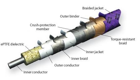
Placing ePTFE binders on either side of the shield (with coefficients of friction as low as 0.02) lets each conductor slide past its neighbors and the outer shield with ease, making the cable as a whole more flexible in rotation and torque, and eliminating internal abrasion. Designers who know a cable will not lose strength over time through abrasion can tighten the design envelope and still extend cable life.

ePTFE Cable

Any cable jacket must protect the shields and conductors from the environment and lend extra tensile and flexural strength. Like conductor insulators, jacket layers should be thin, resist tears, withstand fluid attack, and have high tensile strength.

Many applications use durable polyurethane (PU) jackets. For environments that require low particulation, polyvinylchloride (PVC) may be a better choice.

Jackets can also be made of ePTFE for additional insulation and resistance to chemical attack. If the cable assembly slides through other machine parts, abrasion-resistant ePTFE is a good choice for extending cable life.

The advancements in ePTFE manufacture allow for uniformly thick tapes in running lengths of over 1000 meters. This opens up a world of possibilities for cable manufacture that is only now being harnessed around the world.

Lubring - Special Notes on Bonding and Finishing

As a globally reputed manufacturer of Lubring Slideways, we are frequently asked to provide technical assistance with regards to the bonding and finishing of the material.

Lubring is a slideway bearing material that is used primarily in machine tool building and reconditioning. As such, the machine builder is usually equipped with enough know-how on the bonding and subsequent planing of the material, such that it forms the most effective bearing surface. However, we often supply to dealers or first time builders, who need more assistance on the bonding process.


Preparation:

The metal surface to be mounted with Lubring Slideway can be prepared by the normal machining methods such as grinding, milling, shaping, and planning. The surface roughness of all forms of preparation should be preferably between Ra = 1.6 µm and Ra = 3µm and not more than Ra = 6µm.

Once roughened the surfaces can be cleaned with Trichloroethylene, Perchloroethylene or Acetone. Slideway bearing material should be cleaned similarly.

Bonding:

For bonding of Lubring Slideway the following resin adhesive can be used: Ciba Geigy’s Araldite – Hardener – HV 953U; Araldite AW106. The Araldite should be applied both to metal and slideway and be spread as uniformly as possible by means of a serrated spatula. To obtain the best dispersion of the adhesive, when spreading on the slideway brush in the longitudinal direction; when spreading on the metal, brush in the transverse direction. The total quantity of bonding should be approximately 200gm per sq. mt.

Hardening:

After mounting the slideway a clamping pressure of between 0.1 – 0.3 kp/sq.cm is recommended. It is important to keep the pressure constant during the hardening process. Due to the differences in the thermal expansion coefficient of the materials, the maximum curing temperature should not exceed 40°C. The hardening time for various temperatures is 20°C min 15 hours; 25°C min 12 hours; 40°C min 5 hours.

Finishing:

After curing of the adhesive, the Lubring Slideway can be machined by conventional means. The choice depends on the machinery available viz.: grinding; grindstone.

Grinding: For grinding of Lubring Slideway use the same speed as grinding cast iron, taking care that sufficient cooling is used with an ‘open ’stone. The grindstone should be preferably silicon carbide based with rubber or polyurethane binding; grain size 80-30. Alternatively, aluminum oxide with rubber bonding may also be used for soft, fine grinding action, pre-polishing, and pre-mating treatment.

Oil Grooves: Lubring Slideway can be machined with oil grooves using the same methods and cutting data as used for cast iron. The form and depth of the oil grooves are optional. However, the oil grooves should never pierce through the Lubring Slideway. Oil grooves should be away from the edges by 6mm.

Metal Mating Surface: The metallic mating surface running against the Lubring Slideway should be finished to 16 Ra for optimum performance. The surface finish must never be below 14 Ra or above 20 Ra as applicable to cast iron or steel. This surface finish should be obtained by grinding in the direction of travel. Do not lap or polish to obtain this surface finish.


The above parameters provide an effective guideline not just for Lubring, but for bonding all PTFE-related items to metal.

Do visit our website for more details