Unravelling Polymers

The Definitive Blog on Polymers by Poly Fluoro Ltd.

PTFE Sliding Bearings - Design Considerations

PTFE sliding bearing, sliding plate bearing, ptfe slide bearing plates, sliding bearings, ptfe slide bearings, teflon sliding plate, sliding bearing design, ptfe sliding plate, teflon slide bearing

PTFE sliding bearings are an essential part of any load bearing structure that is likely to experience either thermal or mechanical movement. Despite this, its design and construction remain obscure, with many consultants and civil engineers preferring to leave the bearing’s exact composition and measurements in the hands of the bearing manufacturer.

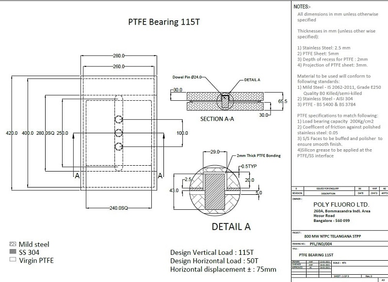
On the face of it, a PTFE sliding bearing - also called a sliding plate bearing, a bridge bearing, a bearing pad or a Teflon sliding plate - is a simple assembly. Primarily, it consists of only 2 layers – a PTFE plate and a polished stainless-steel plate. These two materials are known to have the lowest coefficient of friction between any two solids and slide over each other effortlessly, especially when subjected to high pressures. In order to keep the PTFE in place, a mild steel plate is normally used as a backer. Since PTFE does not bond easily to other materials, this mild steel plate is often recessed, with the PTFE being bonded within the recessed pocket. This ensures the PTFE plate stays in place, even under high shear loads. This mild steel-PTFE combination is called the lower element. Similarly, as polished stainless-steel is expensive and since only a layer of about 2mm is needed anyway, another mild steel plate is used as a backer for the stainless steel. In this case, the stainless steel is stitch welded to the mild steel to ensure that it stays in position over the long term. This mild steel-stainless-steel combination called the upper element.

Having thus defined the basic form of the bearing, the other aspects of design can now begin to take shape. Often, these parameters will be defined by the client, leaving it to the manufacturer to both design the sliding bearing accordingly and prove – using calculations based on material properties – that the specified parameters can indeed be accommodated. These include:

1. Vertical load – possibly the most relevant parameter. A PTFE sliding bearing needs to be able to comfortably hold the compressive load being placed on it. Since steel has a far higher compressive strength than PTFE, the design focusses on the area of PTFE to be used, considering PTFE’s own compressive strength. It should be noted that while PTFE is capable of taking loads as high as 400 Bar (40Mpa), designers would do well to take a safety factor of 50-60% against and consider a compressive strength of 150-200 Bar when making calculations. Once the quantity in square centimetres is established, the exact length and width can be altered to suit the size of the portal plate on which the bearing is to be installed.

2. Longitudinal movement – The whole purpose of a PTFE  sliding bearing is to accommodate movement while taking vertical loads. In the case of certain structures – such as pipelines - the linear thermal expansion of the system can be so high that between morning and noon, the bearing may be required to slide over 100mm in either direction. Movement dictates the extent to which the stainless-steel sheet would be required to extend beyond the PTFE plate.

While on its own, movement seems like a simple matter of adding the value of the total expected movement to the size of the PTFE plate, movement also creates an issue of cantilever loads. The further the upper element extends beyond the lower, the more chances there are of bending. Thus, care also needs to be taken to ensure that the thickness of the mild-steel plate in the upper element is high enough that bending will be avoided

3. Lateral movement – while some sliding bearings are free to slide in all directions (aptly called: free sliding bearings), for the most part, a bearing only needs to slide longitudinally. This means that in the lateral direction, movement would be restricted. To ensure this, either guide plates can be used along the side of the bearings or dowel pins can be incorporated on to the lower element, which would sit inside longitudinal slots on the upper element to prevent lateral movement.

The key consideration here is the extent of lateral load expected. Based on the same, the dowel pin can be designed such that it will not bend.

4. Uplift loads – many structures may experience uplift loads due to either heavy winds or some mechanical characteristics of the system. This can cause a misalignment in the bearing or – in the worst case – even cause the upper element to slip off the lower element completely, causing major structural damage.

Such uplift loads can be accommodated by the use of brackets or a T-shaped dowel pin. Care needs to be taken that the load on the pin does not exceed the tensile strength of the pin itself. To ensure this, we usually employ pins using stainless steel, where the tensile properties allow for higher loads on the same size pin.

In addition to the strength of the dowel pin and/or side guides, it is important to note that a sliding bearing is all about reduced friction. It means little that the PTFE and stainless-steel would slide over one another if there is friction between the guiding elements themselves. Hence, special care needs to be taken to ensure that the gap between the pins and the slots in the bearing are sufficient to allow for free movement. In addition to this, PTFE would need to be used between the slot and the pin to ensure that even if the pin came into contact with the slots, sliding movement would still take place. This is another reason that stainless steel is used for the dowel pin, as it can be polished to ensure a minimal coefficient of friction.

5. Rotation – while most sliding bearings require very minimal rotation (fractions of a degree), there are some assemblies where the flatness of the system could be compromised, causing the upper and lower elements to lose some contact. Employing an elastomer – like neoprene or even silicone – allows the bearing to compensate for this to some extent. Given the nature of the elastomer, higher rotation can only be accommodated by increasing the thickness of the said elastomer, which in turn can cause issues with stability. In such a situation, a spherical bearing arrangement could also be designed in to increase the allowable rotation.
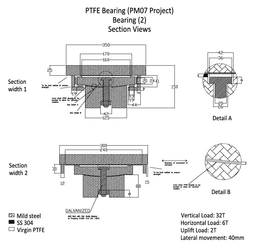
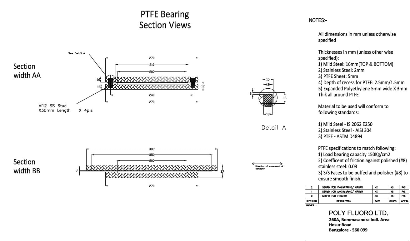
Bearing Section View


Guided Bearing Section View


Guided Bearing Section View

Our own experience with PTFE sliding bearings has shown us that oftentimes, the bearing is the last thing to be designed. In many cases, we have heard that the project has been in the last stages of completion and the bearing was either forgotten or it was otherwise assumed that it was an off-the-shelf item that could be supplied ex-stock! The result of this is that the bearing manufacturer needs to work around constrains such as the size of the portal plate and/or the available gap between the sub and superstructures within which the bearing needs to fit. Sometimes there are even restrictions on welding or bolting, meaning the bearing manufacturer has to design something that can be installed on site with minimal fitment.

The result of all this is that a PTFE sliding bearing is usually a premium product and that a good manufacturer needs to understand all the parameters such that an effective solution can be supplied, often with very little lead time. It is rare that we have even supplied the same bearing twice, because with each new project, the bearing needs to evolve to meet the project’s peculiarities!


Read More

1. Shear Load Considerations for PTFE Sliding Bearings

2. PTFE Sliding Bearings: Calculating Coefficient of Friction

3. Cantilever Load Considerations for PTFE Sliding Bearings

PTFE Lip Seals - Applications, Material Choice & Advantages

The effectiveness of PTFE as a sealing material has been explored before. Whether as a gasket material – such as ePTFE – or as a machined component designed for a specific OEM requirement, PTFE combines an ability to self-lubricate with a capacity for higher temperatures, pressures, and corrosive chemicals to be a highly effective sealing element in nearly all conditions.

While traditional lip seals have used either elastomers or even polyurethane (PU), PTFE lip seals are invaluable in areas where harsher environments call for a more robust polymer. Essentially, PTFE lip seals were designed to bridge the gap between conventional elastomer lip seals and mechanical carbon face seals, as they can operate at higher pressures and velocities when compared to most elastomer lip seals, they are an excellent alternative.

That said, there are many similarities between elastomeric rubber lip seals and PTFE lip seals. When we consider basic construction, both seals use metal casing for structure, a press-fit into a stationary housing gland, and a wear lip material to rub on the rotating shaft.  However, when compared with elastomer lip seals, PTFE lip seals use a far wider lip to shaft contact pattern. PTFE lip seals also make use of a lighter unit loading, but a wider footprint. Their design has taken this direction to address the wear rate, and these changes were made to lower the unit loading, which is also known as PV.

In terms of manufacturing, while elastomeric lips seals allow themselves to be directly moulded onto the metal, PTFE – being a non-injection mouldable material – is machined separately and then press-fitted onto the metal housing. This not only makes it critical to get the dimensions spot-on but also means a more expensive end-product, since PTFE is more expensive than most elastomers and because machining is usually far more expensive than moulding.

The specific application for PTFE lip seals is found in sealing rotating shafts, in particular those with high speed. They offer an excellent alternative to elastomer rubber lip seals if the conditions are challenging and exceed their capabilities.

A good example of PTFE’s superior functionality is in industrial air compressors, where they are configured to provide over 40,000 hours of maintenance-free service.

Other benefits of PTFE lip seals include:

  • Tight sealing, even under high pressure in excess of 35 BAR

  • Ability to run at temperatures far above or below elastomer rubber lip seals (with typical temperature ranges from -53 °C to 232 °C)

  • Elastomer coatings on the seal’s outer diameter make for easy installation without damaging mating hardware

  • Available in custom designs and a wide range of sizes and materials

  • Inert to most chemicals

  • Withstands high speed in excess of 35 m/s

  • Low friction and ability to address rotating equipment and vibration for longer life

  • Compatible with most lubricants and able to run in dry or abrasive media

Dynamic rotary sealing applications for PTFE seals include:

  • Industrial applications - PTFE lip seals replace elastomer and carbon face seals is in the air compressor market

  • Screw Compressors - PTFE lip seals offer excellent leak control and the ability to run at 1,000 to 6,000 RPM with a huge range of lubricants and over extended periods (15,000 hours) to reduce warranty claims

  • Aerospace – PTFE lip seals are used in auxiliary power units (APUs), turbine engines, starters, alternators and generators, fuel pumps, Ram Air Turbines (RATs) and flap actuators, which is one of the largest markets for lip seals

  • Automotive – PTFE lip seals are put to work in some of the most challenging applications in crankshafts, distributors, fuel pumps and cam seals, which are used in the racing industry where naturally, engines are frequently pushed to their limits

  • Turbochargers – PTFE lip seals run at high speeds of 4,000 to 36,000 RPM and can cope with extreme temperature ranges from -40 °F to 350 °F (-40 °C to 177 °C), with limited lubrication over an extended seal life

  • Pumps – PTFE lip seals address dynamic sealing environments, extreme speeds, pressures, and temperatures present in vacuum pumps, along with blowers, chemical pumps, encoders, alternators, drilling and tapping spindles, hydraulic motors and pumps, and air conditioning recovery pumps, among many more applications

Enhancing Performance of PTFE with Fillers

While PTFE has been used liberally across this article, the truth is that PTFE is never just one material. The addition of performance-enhancing fillers allows for augmentation in certain base properties. The selection of these fillers is highly dependent on the application in question.

Several other fillers are used in combination with PTFE. 

  • Modified Virgin PTFE – the same basic properties as virgin, but with increased wear and creep resistance and lower gas permeability

  • Carbon-Graphite Filled - Carbon reduces creep, increases hardness, and elevates thermal conductivity of PTFE. Carbon-graphite compounds have good wear resistance and perform well in non-lubricated applications

  • Carbon Fibre Filled - Carbon fibre lowers creep, increases flex and compressive modulus, and raises hardness. The coefficient of thermal expansion is lowered, and thermal conductivity is higher for compounds of carbon fibre filled PTFE. Ideal for automotive applications in shock absorbers and water pumps

  • Aromatic Polyester Filled - Aromatic polyester is excellent for high temperatures and has excellent wear resistance against soft, dynamic surfaces. Not recommended for sealing applications involving steam

  • Molybdenum Disulphide and Fiberglass Filled - Molybdenum disulphide increases the hardness of the sealing surface while decreasing friction. It is normally used in small proportions combined with other fillers such as glass. MoS2 is also inert towards most chemicals

  • Fiberglass Filled – Glass fibre has a positive impact on the creep performance of PTFE. It also adds wear resistance and offers good compression strength

  • Graphite Filled – Since graphite is often used as a lubricant, it does not significantly increase the coefficient of friction of PTFE when used as a filler. The low friction allows the compound to be used when both shaft speed and pressure are high. Graphite also is chemically inert which enables its use in corrosive media

  • Mineral Filled – Mineral is ideal for improved upper temperatures and offers low abrasion to soft surfaces. PTFE with this filler can easily be qualified to FDA and other food-grade specifications

  • Stainless Steel Filled - Although stainless steel filler is very abrasive, this compound has excellent extrusion and high-temperature resistance in static and slow dynamic applications

  • Other fillers – there is virtually no filler that cannot be combined with PTFE to improve or add to the properties of the material. As long as the filler can to withstand the higher temperatures that PTFE needs to be sintered (cured) at, it can be used. 

Features of Other Machinable Plastics

While PTFE is the most commonly used high-performance plastics for lip seals, there remain other polymers that certainly merit further understanding. Some of these include:

UHMW Polyethylene

  • Excellent wear and abrasive resistance

  • Good lubricity in water

  • Excellent sealing of light gases at low pressures

  • Excellent high-pressure extrusion resistance

  • Moderate abrasion to soft hardware

  • Excellent wear resistance in reciprocating applications

Thermoplastic (TPE) Elastomer

  • Excellent wear and extrusion resistance

  • Excellent sealing of light gases at low pressures

  • Excellent high-pressure extrusion resistance

  • Low abrasion to soft dynamic hardware material

  • Minimum dynamic surface hardness 25 Rc

  • Excellent wear resistance in reciprocating applications

  • Good wear resistance in rotary applications

Polychlorotriflouroethylene (PCTFE)

  • Excellent electrical properties

  • Stable for continuous usage until 205°C

  • Low creep at room temperature

Polyetheretherketone (PEEK)

  • Chemically inert

  • Very strong and rigid

  • Temperature range -60 to 300°C

  • Excellent abrasion resistance


Read More

1. Can Indian Manufacturing Survive COVID?

2. The Challenge of Injection Moulded High-Performance Plastics

3. Polymer Prices Go to the Moon

4. Applications and Considerations for PTFE Seals

Case Study - Cross Directional Expanded PTFE Gasket Tape

The challenges thrown by PTFE as a material are myriad. As we have already illustrated in various articles, the processing techniques needed for PTFE differ from those of other polymers so dramatically, that nearly every end-product requires a special-purpose machine that can be used for no other plastic. The main reason for this is that PTFE is not melt-processable. As a result, heating the polymer into a liquid state to then either mould or extrude it is not possible. Hence, we end up with processes such as paste extrusion (PTFE Tubes), skiving (PTFE tapes), and isostatic moulding (moulded PTFE parts).

Even within the space of PTFE, expanded PTFE (ePTFE) remains an anomaly in terms of processing complexity. We have covered in earlier articles that ePTFE depends on a minimum of nine different parameters, including the grade of material, the nature of the lubricant, the extrusion process, and the stretching process – to name only a few. Each of these parameters needs to be kept in range, with any deviations only revealed once the final product is out – at which point it is too late to make any changes.

While we have mastered the process of making mono-axial ePTFE gasket tapes – the standard ePTFE tape used in industrial applications – cross-directional tapes are another issue altogether. In this article, we look at the development of the same and what advantages it affords.

Difference between mono-axial and cross-directional gasket tape

The main issue with mono-axial ePTFE gasket tapes is that due to the orientation of the fibrils being in only one direction, the material is susceptible to tearing/splitting when tension is applied in the transverse direction. On the other hand, the material exhibits immense compressibility, allowing it to form a perfect seal with minimal pressure and retain its form over a range of temperatures. As such, the tape works brilliantly in applications such as flange-to-flange connections, where the assembly is not intended to be dismantled frequently, once installed.

However, in applications where the frequent opening of the system occurs, the mono-axial tapes fail over the medium-long term. For example, using mono-axial tape along the rim of a vessel that is opened multiple times a day would not work, since the constant application and relaxation of pressure would cause the fibrils to come loose and the tape to slowly disintegrate. Furthermore, with very poor recovery – mono-axial tape is soft but lacks elasticity – the seal becomes less effective each time the lid is closed and opened again.

To remedy this, we set out to create a cross-directional tape that would allow for strength in the transverse direction and be ideal in applications where recovery was needed. Within the industry, there are already ePTFE sheets that are made using multi-directional ePTFE layers. However, these sheets are prohibitively expensive, come in standard sizes of only 1.5mt x 1.5mt, and do not incorporate any fillers. The aim was to:

  1. Develop a low-cost tape to match the properties of multi-directional ePTFE sheets

  2. Create a highly customisable process in-house so that key properties such as compressibility, density, and thickness can be matched to suit the exact OEM requirement

  3. Incorporate fillers such as silica and barium sulphate to reduce creep and add stability to the material


Mono-axial ePTFE Tape

Cross-directional ePTFE Tape

Units

Standard

Specific Gravity

0.35-0.85

1.5-1.9

-

AMS 3255A

Tensile Strength

10-15

20-30

Mpa

AMS 3255A

Compressibility

60%

10-15

%

ASTM F 36

Recovery

-

40

%

ASTM F 36

The result

As the table above shows, the results were rather impressive. While the exact process remains proprietary, the use of special mixing techniques along with calendaring, drying, layering, and curing resulted in an enhancement of properties. The tensile strength was high in both lateral and longitudinal directions. Compressibility was understandably reduced, but the improvement in recovery meant that the material could be used in areas where pressures were erratic. Most importantly, with strength in both directions, there is no chance of any disintegration in the longer term.

By modifying the process slightly, we can influence the compressibility, thickness, and density. Further, the addition of fillers greatly arrests the cold flow of the material, meaning that long term application is more stable, as there is no risk of excess deformation slowly affecting the sealing effectiveness of a gasket.


Read More

1. Case Study - Development of a 4-axis PEEK Valve

2. Over-moulding PTFE on to Stainless Steel